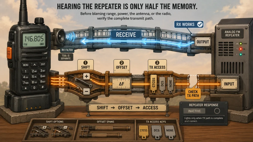
A repeater memory can receive perfectly and still fail when you transmit because the displayed frequency is only one part of the path. The radio must listen on the repeater output, transmit on the correct input, apply the required shift and offset, and send the access tone or code listed for that system. I use a simple rule here: verify the complete transmit path before blaming range, power, or the radio. This guide covers analog FM repeater settings only, not DMR, System Fusion, D-STAR, talkgroups, color codes, or reflectors.
Why a Correct-Looking Repeater Memory Can Still Fail
The first trap is that the main frequency on the screen usually represents only the side of the channel your radio receives. A memory can therefore look correct while its transmit path is still wrong. You may hear a net clearly, press the push-to-talk button, and get no repeater response because the radio transmitted on the output frequency, shifted in the wrong direction, used the wrong offset amount, or sent no access tone.
This is why I separate a repeater memory into four checks instead of treating it as one frequency. The receive frequency tells the radio where to listen. The transmit frequency tells it where the repeater listens. The access setting tells the repeater whether to accept the signal, while the receive-squelch setting controls what your own speaker is allowed to play.
Key point: Hearing a repeater proves that your receive path works. It does not prove that your transmit frequency, offset, tone mode, or signal path is correct.
If you are still building the larger channel plan around these fields, start with the complete ham radio programming process. The purpose of this article is narrower: to make the offset and tone fields understandable before you save them.

BTECH UV-5X3 is an amateur handheld designed for VHF, 1.25-meter, and UHF operation. Its repeater programming supports frequency offsets together with CTCSS and DCS access settings. The radio provides 128 memory channels and can be programmed from the front panel or through supported computer programming software.
Check On AmazonIf you click this link and buy, we earn a commission at no additional cost to you.
Repeater Output and Input Frequencies Do Different Jobs
An analog FM repeater receives on one frequency and retransmits on another, so the repeater input and output frequency fields serve different jobs. The frequency published as the repeater output is the one your radio monitors. When you press the push-to-talk button, the radio must move to the repeater input frequency so the repeater can hear you.
Most radios display the output while the channel is idle because that is the frequency you are listening to. Some radios briefly show the transmit frequency when keyed, while others leave the output displayed and indicate only a plus or minus shift symbol. The display behavior is radio-specific, so the reliable check is the programmed transmit frequency, not what you assume the screen is showing.
| Setting | What it controls | What happens if it is wrong |
|---|---|---|
| Output frequency | Where your radio listens to the repeater | You hear nothing or monitor a different system |
| Input frequency | Where your radio transmits to the repeater | The repeater does not receive your signal |
| Shift direction | Whether transmit moves above or below the output | The calculated transmit frequency lands on the wrong side |
| Offset amount | How far transmit moves from the output | The radio transmits on the wrong input even if the direction is correct |
| Access tone or code | What the repeater may require before opening | Your signal reaches the input but the repeater may ignore it |
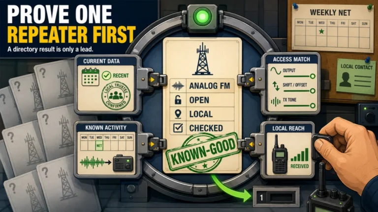
Before programming anything, confirm the current listing rather than copying a frequency from an old memory or a screenshot. The process in finding a usable local repeater matters because a directory result is only useful when its output, input relationship, access method, and operating status are current.
Shift and Offset Must Be Read as One Instruction
The plus or minus symbol cannot be interpreted by itself. It tells the radio which direction to move from the output frequency, while the offset tells it how far to move. A minus shift places the transmit frequency below the output, and a plus shift places it above. A direction without an amount is incomplete, and an amount without a direction is equally incomplete.
For example, suppose a listing shows an output of 146.940 MHz, a minus shift, and an offset of 0.600 MHz. The radio listens on 146.940 MHz and transmits on 146.340 MHz. That is an illustration of the calculation, not a rule that every repeater uses the same direction or spacing.
Common offset conventions are useful for spotting obvious mistakes, but local and regional band plans, coordination, border conditions, and individual repeater assignments can change the expected result. I treat an automatic or conventional offset as a starting guess only. The listing and the resulting transmit frequency are the configuration that matter.

Radioddity GA-510 is a VHF and UHF handheld that supports manual repeater programming from its keypad. Radioddity documents separate controls for repeater shift direction, frequency offset, transmit CTCSS tone, power level, and memory storage. The radio provides 128 memory channels and also supports CTCSS and DCS operation.
Check On AmazonIf you click this link and buy, we earn a commission at no additional cost to you.
A CTCSS Tone Opens Access, but It Does Not Hide Your Signal
CTCSS stands for continuous tone-coded squelch system. A radio adds a low-frequency tone to the transmitted audio, and a repeater configured for that tone can use it as a condition for opening its receiver or passing the signal. The tone may also be called a PL tone in listings or radio menus, although the exact label varies.
The tone is an access tool, not security, encryption, or a private channel. Other stations can still receive the analog FM transmission without decoding secret information because there is no secret information to decode. The tone simply helps a receiver respond to the intended signal and ignore carriers that do not include the expected tone.
A listing that shows a transmit tone of 100.0 Hz means your radio must send that tone while transmitting. Entering 100.0 in a tone field is not enough by itself if the radio’s tone mode remains off. Both the value and the mode that activates it must be correct.
Field Note: One of the easiest beginner mistakes to miss is a correct tone number paired with the wrong tone mode. The screen or programming file looks convincing because the number is present, but the radio never actually sends it.
Tone vs Tone Squelch: Where TSQL and Cross Mode Fit
Menu labels change from one radio or programming tool to another, but the decision underneath them stays the same: what should the radio send, and what should be allowed to open its speaker? For a typical repeater that requires only a CTCSS access tone, the practical choice is transmit tone with ordinary carrier squelch on receive. That sends the required tone without muting valid repeater audio at your speaker.
TSQL, tone squelch, or tone decode usually means the radio sends a CTCSS tone and also requires a matching tone on received audio before opening the speaker. That can be useful when the repeater intentionally transmits the expected tone, but it adds another failure point. If the listed receive tone is missing, outdated, different from the transmit tone, or not transmitted by the repeater, your radio may stay silent while the signal is present.
| Common label | Transmit behavior | Receive behavior | Typical use |
|---|---|---|---|
| None, Off, or Carrier | No CTCSS tone or DCS code | Carrier-operated squelch | Repeaters with no access tone or ordinary simplex |
| Tone, Encode, or T | Sends the selected CTCSS tone | Carrier-operated squelch | Common analog repeater access |
| TSQL, Tone Squelch, or Encode/Decode | Sends a CTCSS tone | Requires the configured receive tone | Use only when the repeater listing supports it |
| Cross | Uses one selected method or value | Uses a different method or value | Systems with separate transmit and receive conditions |
Cross mode is not automatically better or more advanced. It is simply the method used when the transmit side and receive side do not match, such as transmitting CTCSS while decoding DCS, or using different CTCSS values in each direction. Do not select it because it sounds comprehensive; select it only when the current system data requires that exact relationship.
A handheld and a mobile or base radio may expose that same relationship in very different ways. One may provide separate transmit and receive fields, while another may hide the combination behind a single tone-mode choice or a cross-mode menu. The radio type does not tell you which behavior to expect, so confirm the field mapping in the exact manual before copying settings from another radio.
Software can make these fields easier to see, but it does not remove the need to understand them. The field mapping in programming a radio with CHIRP should be checked against the exact radio profile, while the menu names used for front-panel radio programming must come from that radio’s manual.
Some Repeaters Use DCS or No Access Tone
Not every analog FM repeater uses CTCSS. Some listings specify DCS, which may appear in a radio or software as DCS, DTCS, digital code, or a similar label. In that case, the code and sometimes its polarity must match the system data; entering a CTCSS frequency will not substitute for it.
Other repeaters use carrier access and require no tone or code at all. Leaving the tone mode off is correct for those systems. A beginner can create a problem by assuming every repeater needs a tone, just as easily as by omitting one when it is required.
Note: Older manuals and forum posts may mention a tone burst. That is a brief access signal, not another name for the continuous CTCSS tone sent while you transmit. Do not enable a burst option for a current U.S. repeater unless its current listing or operator documentation specifically requires it.
- If the listing shows a CTCSS transmit tone, enable the transmit-tone mode and enter that frequency.
- If the listing shows DCS or DTCS, select the matching digital-code mode and enter the listed code.
- If the listing shows no access tone, leave tone and code transmission disabled.
- If separate transmit and receive values are published, use the exact radio manual to map them to cross-mode fields.
The important distinction is that DCS is a coded squelch method used with analog FM audio; it is not the same thing as a digital voice system. That difference keeps this configuration inside the analog repeater path covered here.

Yaesu FT-65R is a 2-meter and 70-centimeter FM handheld transceiver with 200 programmable channels. Yaesu lists built-in CTCSS and DCS operation for analog access and selective calling. It also provides three selectable transmit power settings of 5W, 2.5W, and 0.5W.
Check On AmazonIf you click this link and buy, we earn a commission at no additional cost to you.
Automatic Repeater Shift Is Helpful, Not Proof
Many radios can apply an expected plus or minus shift automatically when you tune within parts of an amateur band. This can save time in variable-frequency mode and may produce the correct input for a conventional local repeater. It does not verify the directory entry, the offset amount, the access tone, or an unusual local assignment.
The safest check is simple: compare the listing’s input information with the actual transmit frequency the radio will use. If the radio shows only an offset symbol, use its reverse, transmit-check, or memory-detail function if available, following the manual. If the radio does not provide a safe way to inspect the value on screen, read the programmed channel back through its supported programming method.
Warning: Do not key the transmitter repeatedly just to discover where the radio is transmitting. Inspect the channel data first, then make one identified test when the frequency is clear and the repeater is not carrying traffic.
Automatic shift should reduce button presses, not replace verification. Once the channel is saved, recall the memory and recheck it rather than assuming the settings remained attached to the frequency.
Use This Diagnostic Sequence Before Changing Everything
When a repeater does not respond, changing several fields at once makes the result harder to interpret. Work from receive toward transmit and separate configuration failure from coverage failure. I would not raise power or replace an antenna until the stored transmit path is proven correct.
- Monitor the output first. Confirm the frequency is active, the audio sounds like the intended repeater, and no conversation is in progress.
- Check the output frequency. Compare the recalled memory with the current listing, including every decimal place.
- Inspect the transmit frequency. Verify the plus or minus direction and offset amount produce the listed input.
- Verify the access method. Confirm CTCSS, DCS, or no tone, then make sure the selected mode actually transmits it.
- Disable unnecessary receive tone squelch. For diagnosis, ordinary carrier squelch removes one possible reason the speaker stays muted.
- Start with appropriate low power. If you are reasonably close and have a clear path, use enough power for a clean test without defaulting immediately to maximum.
- Make one identified test. State your call sign and that you are testing, then listen for the repeater’s response, courtesy tone, tail, or another operator’s report.
A repeater tail or courtesy tone suggests that the system recognized something, but it does not prove your audio is clear or that you have a reliable path. A full signal report from another operator is more useful than repeatedly keying and releasing the transmitter. FCC identification rules also apply to test transmissions, so an unexplained carrier is not the right diagnostic tool.
If the memory passes these checks but access remains unreliable, move beyond offset and tone into location, terrain, antenna connection, power, battery condition, and receiver behavior. The ham radio troubleshooting sequence helps keep those next checks in a useful order.
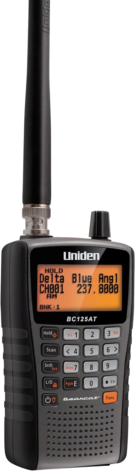
Uniden BC125AT is an analog handheld scanner with 500 alpha-tagged channels. Its supported ranges include the 2-meter and 70-centimeter amateur bands, allowing analog repeater output frequencies in those ranges to be monitored without transmitting. The scanner also provides Close Call RF capture and programmable channel banks for organizing monitored frequencies.
Check On AmazonIf you click this link and buy, we earn a commission at no additional cost to you.
Digital Repeater Settings Belong to a Different Configuration Path
DMR, System Fusion, and D-STAR can use the same general idea of a repeater input and output, but their access and routing fields are not substitutes for CTCSS or DCS. A DMR color code, talkgroup, time slot, or contact is part of a digital configuration. D-STAR routing fields and System Fusion operating modes follow their own radio and network documentation.
Do not try to solve a digital access problem by changing analog tone squelch fields. First confirm whether the repeater channel you found is analog FM, digital-only, or mixed-mode. Then use the documentation for that system and the exact radio, because the analog settings explained here cover only the FM path.
This boundary matters when a directory lists several modes on one site or frequency pair. The presence of a familiar offset does not mean every mode uses the same access fields. Identify the operating mode before building the memory, then configure only the fields that belong to it.
Final Thoughts: Verify the Transmit Path, Not Just the Display
A working analog repeater memory is a small system: output frequency for listening, input frequency for transmitting, the correct shift and amount, and the access method the repeater expects. Tone squelch on your receiver is optional unless the listing gives you a reason to use it. Automatic shift and programming software can fill fields quickly, but neither one proves the finished memory is correct.
My final check is to recall the saved channel and read it as a complete path before transmitting. If the output, calculated input, and tone mode all match the current listing, then a careful identified test can tell you whether the remaining issue is coverage or signal quality. That order prevents a receive-only success from hiding a transmit-side mistake.
FAQs
📻 Which repeater frequency should I enter into the main frequency field?
Enter the repeater output frequency as the main receive frequency unless the exact radio or software requires a different format. The shift and offset, or a separate transmit-frequency field, then define the repeater input.
↕️ What is the difference between repeater shift and offset?
Shift is the direction, plus or minus, from the output to the input. Offset is the amount of frequency separation. You need both pieces, or the exact input frequency, to know where the radio will transmit.
🎵 Do I need CTCSS tone and tone squelch together?
Usually not. A repeater may require a transmit CTCSS tone while your receiver remains on ordinary carrier squelch. Enable TSQL only when the repeater listing supports the receive-tone requirement and you want that filtering.
🔇 Why can I hear the repeater but not transmit through it?
Your receive frequency can be correct while the transmit frequency, shift, offset, or access tone is wrong. Verify those fields first, then consider distance, terrain, antenna performance, and power.
⚙️ Does automatic repeater shift also set the CTCSS tone?
Do not assume it does. Automatic shift normally addresses the transmit-frequency relationship, while tone data may require a separate entry. Check the recalled memory against the current repeater listing.
🔢 Is DCS the same as a digital voice repeater mode?
No. DCS is a coded squelch method that can be used with analog FM. Digital voice systems use separate access and routing fields defined by that mode and radio.