The best first HF wire antenna is the one you can install safely, feed correctly, tune in its final position, and keep in the air. I would not choose between a center-fed dipole, an inverted V, and an end-fed half-wave until I knew the bands, available span, support points, feedline route, and property restrictions. A dipole is usually the easiest system to understand, an inverted V can solve a support problem, and an end-fed half-wave can solve a feed-point problem, but each choice moves complexity somewhere else. The practical goal is not a perfect drawing or a tuner-friendly display; it is a complete antenna system that measures sensibly and operates within electrical, structural, lightning, and RF-exposure limits.

Choose the Site Before You Choose the Wire Design
For ham radio beginners, an HF wire antenna should start as a property decision, not a catalog decision. The first questions in the complete antenna setup process are which bands you expect to use, how much clear span exists, where the feed point can sit, how high the supports can safely carry the wire, and how the feedline will enter the station. A design that looks simple on paper can become the wrong first antenna when its center lands over a roof, its ends cross a walkway, or its coax route requires a risky climb.
- Bands: Identify the lowest band you genuinely plan to use, because lower frequencies usually require more wire and more space.
- Span: Measure the usable distance between safe support points, not the property-line distance shown on a map.
- Feed point: Decide whether the coax can reach the center, or whether an end feed is the only practical route.
- Height: Record realistic support height without assuming a roof or tall tree is automatically safe to access.
- Entry: Plan the coax path, bend radius, drip loop, weather sealing, and transition into the station.
- Access: Keep energized wire and feed-point hardware away from people, pets, ladders, metal gutters, and routine yard work.
| Design | Site condition it solves | Complexity it adds |
|---|---|---|
| Center-fed half-wave dipole | You can route feedline to the center and support both wire ends | Requires a practical center feed point and usually the most horizontal span |
| Inverted V | You have one useful high center support but limited horizontal span | Leg angle, lower end height, and nearby ground can change the match and pattern |
| End-fed half-wave | The feedline can reach one end more easily than the center | Requires the correct matching network plus deliberate common-mode and voltage management |
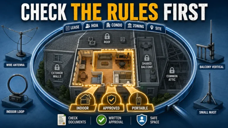
I have seen HOA restrictions quietly end a home antenna project before the operator reached the tuning step. That is why I recommend making a site sketch before calculating wire length. For U.S. operators, PRB-1 concerns state and local land-use regulation; it does not override private HOA covenants, CC&Rs, or rental agreements. Confirm those limits before buying wire or placing permanent supports.

This QWORK open-reel tape is 1/2 inch wide and extends 330 feet with dual-sided markings. The tape is made from fiberglass, and the listing describes it as water resistant. It also has an ergonomic handle and is intended for engineering, yard, and field measuring.
Check On AmazonIf you click this link and buy, we earn a commission at no additional cost to you.
A Center-Fed Dipole Is Predictable, Not Pre-Finished
A center-fed half-wave dipole is often the clearest first system because the two wire legs and the feed point are easy to visualize. The familiar starting formula for total length in feet is 468 divided by the target frequency in MHz, with the result split into two legs. Treat that number as cutting guidance, not a guaranteed finished dimension. Conductor diameter, insulation, height, nearby trees, roofs, metal, soil, and the angle of the wire can all move the resonant point.
Build the antenna slightly long, install it in the position where it will operate, and measure before making permanent cuts. If the SWR minimum is below the desired frequency, shorten both legs equally in small steps. If the minimum is above the desired frequency, the antenna is electrically short, so further cutting moves it in the wrong direction. Folding wire back on itself during early adjustments can preserve options while you learn how the installed antenna responds.
Key point: Do not cut a dipole to a formula, test it on the ground, and call the result final. The useful measurement is the one taken after the antenna is supported, routed, and configured as it will be used.
A resonant dipole also does not promise exactly 50 ohms at every height and location. Its feed-point impedance changes with electrical height, ground, orientation, and surroundings, so a low but imperfect SWR can be normal. The better beginner question is whether the antenna is resonant where you need it, whether the radio and feedline can handle the measured match, and whether the system remains stable in ordinary weather.

This 1:1 current balun is specified for 1 to 54 MHz operation in the verified 2000W variant. Its listing identifies 50-ohm Yagi, V-type, and dipole antenna use and describes a 64 mm ferrite core. The enclosure is listed as waterproof and UV-resistant for outdoor antenna installations.
Check On AmazonIf you click this link and buy, we earn a commission at no additional cost to you.
Use an Inverted V When One Center Support Is Your Best Asset
An inverted V is still a center-fed dipole, but its legs slope down from one high feed point. This can reduce the horizontal span and make one strong center support more useful than two equally high end supports. It is often a practical layout when a straight dipole would cross a boundary or when the coax can descend directly from a central tree or mast.
The trade-off is that the sloping legs change the antenna’s geometry. As the included angle becomes tighter and the ends move closer to the ground, feed-point impedance, radiation pattern, and interaction with nearby objects can change. Avoid treating a diagram angle as a universal target. Keep the legs as open and symmetrical as the site safely allows, then measure the installation.
Decision rule: Choose the inverted V because it fits one safe center support and a shorter span, not because it is automatically better for local or distant contacts. Its operating behavior still depends on band, electrical height, ground, orientation, and current propagation.
Low wire ends deserve special attention. They should not become clothesline-height hazards, touch vegetation that people regularly handle, or terminate where a child, pet, gardener, or delivery worker can reach them. Use nonconductive end support where appropriate, provide strain relief, and keep the ends well clear of metal fences and gutters.

This QNR utility rope is 100 feet long and uses 3/16-inch solid-braid black polyester. The listing describes the cord as low stretch with high UV and abrasion resistance. The verified listing is the single 3/16-inch size rather than the separate two-pack variant.
Check On AmazonIf you click this link and buy, we earn a commission at no additional cost to you.
An End-Fed Half-Wave Moves the Feed Point, Not the Work
An end-fed half-wave can be attractive when the station is near one end of the available wire path. The coax and matching unit can remain near a wall, lower support, or portable operating position while the wire extends away from the station. For a beginner, that convenience is real, but it should not be confused with a wire connected directly to 50-ohm coax.
The end of a half-wave wire presents a high impedance, so the system needs a matching transformer designed for that job and for the intended power level and bands. The feed point can also develop high RF voltage. Keep the matching unit and exposed conductors away from touchable locations, wet surfaces, combustible material, and places where people can reach them during transmission.
The return path is installation-dependent. Some systems use a defined counterpoise, some rely partly on the coax shield, and many benefit from common-mode control placed where measurement or the antenna documentation indicates. There is no honest universal counterpoise length or choke position for every end-fed installation. Coax length, routing, grounding, nearby conductors, transformer design, and the bands in use can all change the result.
Multiband operation also needs realistic expectations. A wire may present usable resonances on several harmonically related bands, but that does not guarantee a low SWR across every portion of each band or compatibility with every built-in tuner. Measure every band you plan to transmit on, and do not assume one successful check proves the system is ready everywhere else.

This end-fed half-wave is listed for the 10, 15, 20, and 40 meter bands. The JYR4010-150W model uses a 1:64 matching balun and is the verified 150W variant. The listing presents it as a long-wire ham radio antenna for POTA and SOTA use.
Check On AmazonIf you click this link and buy, we earn a commission at no additional cost to you.
Know What an Antenna Tuner Can and Cannot Fix
An antenna tuner transforms the impedance presented to the radio so the transmitter sees a load it can accept. It does not retune the physical wire, remove loss already occurring in the feedline, repair a wet connector, or make an unsafe installation safe. A low SWR at the radio after tuning therefore proves only that the tuner created an acceptable match at that point.
This distinction matters most when high SWR exists on a length of coax between the tuner and antenna. The mismatch remains on that section of line, and the resulting loss depends on frequency, feedline type, length, and the size of the mismatch. A tuner can protect the transmitter from an unacceptable load while part of the signal is still being lost before it reaches the antenna.
Stop condition: Stop transmitting if the match changes sharply with rain, wind, coax movement, connector handling, or power level. Those changes can indicate water entry, arcing, a loose connection, heating, or common-mode current, none of which should be hidden with repeated tuning.
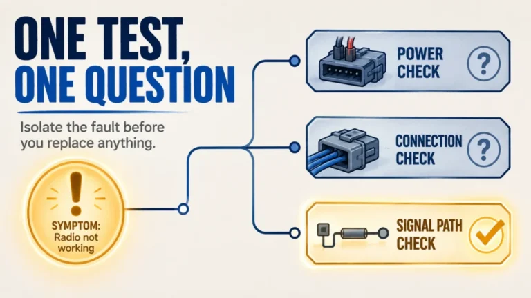
Built-in tuner range is model-specific, so check the exact radio manual rather than assuming every internal tuner handles the same impedance range. If the tuner works on one band but refuses another, do not keep transmitting into the fault and call it a tuner limitation. First inspect the antenna, feedline, connectors, band selection, and measured impedance.

The ATU-100 EXT is an automatic ham radio antenna tuner listed for 1.8 to 55 MHz. Its Amazon listing describes automatic impedance matching and a compact design. The model is marketed for POTA, SOTA, and DX operating contexts.
Check On AmazonIf you click this link and buy, we earn a commission at no additional cost to you.
Treat Feedline and Common Mode as Part of the Antenna
Most beginner HF stations use 50-ohm coax because it is mechanically convenient and compatible with common radio outputs. Choose the cable by frequency, length, loss, outdoor rating, connector fit, and routing requirements rather than diameter alone. The practical details in choosing coax cable and connectors matter because a good wire cannot recover power lost in damaged, waterlogged, or poorly terminated feedline.
At a balanced dipole feed point, a current balun or common-mode choke is commonly used to reduce unwanted current on the outside of the coax shield. An end-fed system may need common-mode control for a different reason because the feedline can become part of the return path. The correct location and choking impedance depend on the antenna and installation, so avoid copying a fixed number of coax turns without confirming that it is appropriate for the bands and cable involved.
Common-mode current can show up as RF on the microphone or radio case, computer or audio disruption, unstable SWR when the coax moves, unexpected noise changes, or reports that transmitted audio becomes distorted at higher power. These symptoms do not prove a single cause, but they justify checking the feedline route, bonding, choke placement, connector condition, and antenna balance before adding more power.
Key point: If moving the coax changes the antenna measurement, the coax may be acting as more than a feedline. Stabilize the routing and investigate common mode before final trimming, or you may tune the antenna to a temporary cable position.
Route coax away from sharp edges, standing water, hot surfaces, and places where it can be crushed by a window or door. Form a drip loop before an outdoor entry point, weatherproof exterior connectors with a removable system intended for that exposure, and provide strain relief so the connector does not carry the weight of the cable.

This YOTENKO kit uses 50-ohm RG58 coax in the verified 49.2-foot variant. It uses UHF PL-259 cable connectors and includes a four-piece UHF adapter kit covering SMA, BNC, and SO-239 connections. The listing identifies amateur radio and SWR meter use.
Check On AmazonIf you click this link and buy, we earn a commission at no additional cost to you.
Height Changes the Pattern, but It Does Not Create One Universal Result
A wire antenna’s physical height becomes electrical height when compared with wavelength. The same support height can therefore place an antenna at a very different fraction of a wavelength on 10 meters than on 80 meters. Ground characteristics, wire orientation, slope, nearby structures, and propagation then interact with that electrical height.
This is why fixed statements such as “hang it low for NVIS” or “put it at one-half wavelength for DX” are incomplete beginner rules. Height can change the elevation pattern, but the signal that reaches another station also depends on the band, time, ionospheric conditions, noise, terrain, and the other station’s location. A lower antenna is not guaranteed to produce useful near-vertical incidence skywave, and a higher antenna is not guaranteed to produce a distant contact.
Practical comparison: If two positions are both safe, document the support height, orientation, band, time, and received reports before deciding which one works better. Without those conditions, “higher was better” or “lower was better” is only a story about one contact.
Use height as a controlled improvement: clear people and nearby obstructions, reduce coupling to the house and soil where practical, and raise the wire only with supports that remain structurally and electrically safe. Then compare real reports and measurements over time instead of treating one contact as proof of a universal pattern.
This QNR rope is a 100-foot hank of 1/4-inch solid-braid black polyester. The listing describes it as low stretch with high UV and abrasion resistance. The verified child ASIN is the 100-foot hank rather than the separate 500-foot spool variant.
Check On AmazonIf you click this link and buy, we earn a commission at no additional cost to you.
Set Safety Stop Conditions Before the Wire Goes Up
No HF contact is worth placing a wire, ladder, mast, throw line, tree limb, or person where it could contact an overhead power line. Do not install where any part of the antenna or support could fall, swing, or be carried into an energized conductor. If power-line clearance is uncertain, stop and use another location; do not attempt to measure clearance from a ladder or roof.
Inspect trees and branches from the ground for dead wood, cracks, decay, storm damage, and movement that could saw through or overload the wire. Do not climb a tree, roof, or mast without the training and equipment required for that work. When the installation needs elevated access, structural evaluation, drilling through a building envelope, or a permanent mast, hand that part to a qualified professional who can assess the site and local code requirements.
Allow supports to move without transferring destructive tension to the wire or building. Keep the antenna and feed point away from public access, and do not work on the system during a storm or when lightning is nearby. Lightning protection, bonding, grounding electrodes, entrance-panel work, and building-code compliance are not solved by adding a random ground rod; use the grounding and lightning protection framework and obtain qualified help where the service entrance or local code is involved.
- Stop if the antenna or any support could reach a power line in any failure direction.
- Stop if safe access requires an untrained roof, tree, tower, or mast climb.
- Stop if a support shows rot, cracking, storm damage, excessive movement, or uncertain loading.
- Stop if people can touch the wire, feed point, transformer, or counterpoise during transmission.
- Stop installation and disconnect outdoor work when a storm is present or approaching.
- Stop before modifying building grounding, bonding, or the electrical service without code-qualified guidance.
RF exposure is another design input, not an afterthought. U.S. amateur stations must be evaluated for compliance with applicable exposure limits, and the evaluation should reflect frequency, power at the antenna, mode duty cycle, antenna gain, pattern, and accessible areas. Complete the evaluation before routine transmission and reassess it when power, antenna, placement, gain, or operating pattern changes. The RF exposure safety process explains how to separate controlled household conditions from public or uncontrolled exposure.

This Proxicast gas-discharge-tube coaxial arrester is listed for 0 to 3 GHz operation with a 230V rating. The verified child ASIN is the UHF female-to-female SO-239 variant. It is intended for RF antenna systems including HF, VHF, UHF, CB, ham, and two-way radio applications.
Check On AmazonIf you click this link and buy, we earn a commission at no additional cost to you.
Tune and Verify the Antenna in a Repeatable Sequence
Measure the antenna after it is installed at its operating height with the feedline routed as it will remain. Before connecting an analyzer, confirm that no transmitter is connected to the same line and that the analyzer is configured for the expected frequency range. Calibrate at the measurement reference plane when the instrument and test method require it, following the analyzer’s own instructions rather than assuming every device uses the same calibration steps.
Start with a sweep wider than the desired operating segment so you can see where the SWR minimum actually falls. A narrow sweep can make the screen look good while hiding the fact that resonance is outside the intended band. Record the frequency of the minimum, the SWR there, and the SWR at both ends of the segment you expect to use.
- Inspect the wire, supports, feed point, coax, and connectors before measuring.
- Install the antenna in its final geometry and stabilize the feedline route.
- Run a wide analyzer sweep with the transmitter disconnected.
- For a dipole or inverted V, adjust both legs equally and in small steps.
- For a multiband end-fed system, recheck every intended band after each meaningful adjustment.
- Confirm the result at low transmitter power using the station’s SWR indication or external meter.
- Document final dimensions, support height, orientation, feedline length, choke location, and measured bandwidth.
Research-based setup: Make the smallest reversible change first. Folding or repositioning a short wire section, stabilizing the coax, or correcting a connector is easier to undo than cutting several inches because one measurement looked high.
Do not trim only toward the lowest possible SWR number. Place the usable bandwidth where you actually operate, and remember that an antenna can be acceptable without reaching 1:1. The detailed low-power SWR checking procedure helps separate a normal match from a fault that should stop transmission.
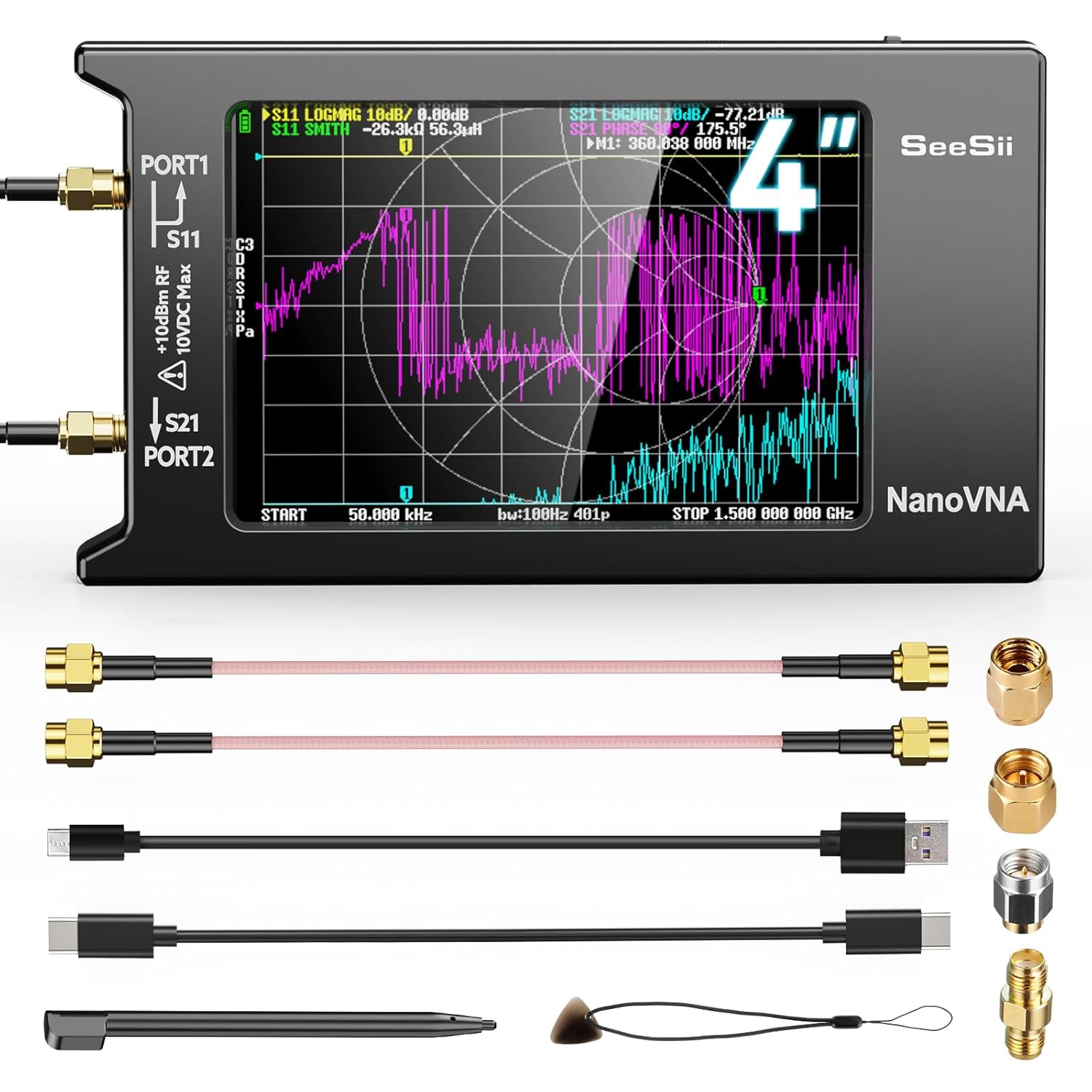
The NanoVNA-H4 covers 9 kHz to 1.5 GHz and is designed for antenna and network measurements. It measures S parameters, SWR, phase, delay, and Smith-chart data on a 4-inch display. The listing also specifies a 1950 mAh battery for portable measurement work.
Check On AmazonIf you click this link and buy, we earn a commission at no additional cost to you.
Hand the Finished Antenna Off to the Complete HF Station
A wire in the air is not yet a complete operating path. The radio needs a suitable power source, the coax and connectors must carry the intended power, the measured SWR must stay within the radio’s operating limits, and grounding, lightning planning, and RF exposure must match the installation. Increasing transmitter power should come after those checks, not before them.
If the radio itself has not been chosen, work backward from bands, modes, power needs, tuner expectations, and how the station will be used. The guide to choosing an HF radio by use case keeps the antenna and radio decisions connected without assuming a particular model. A radio with a wider tuner range does not remove the need for a sound antenna system, and a well-matched antenna does not correct an undersized power or feedline installation.
Station handoff: Antenna geometry, matching, coax, SWR, power, grounding, lightning planning, and RF exposure are one system. A green indicator on any single component does not certify the rest.
Before the first routine transmission, verify the complete path at low power. Listen for local noise, confirm that controls and connected electronics remain stable, check for unexpected heating or arcing, and make sure nobody can enter an RF-exposure or touch-hazard area. Increase power only when the system remains stable and the exposure evaluation supports the operating condition.

This SKY TOPPOWER bench supply converts 110V AC to regulated 13.8V DC. The listing specifies 30A maximum output and 20A continuous output, with screw-type terminals and a front socket rated to 10A. It includes analog voltage and current metering plus short-circuit and over-current protection.
Check On AmazonIf you click this link and buy, we earn a commission at no additional cost to you.
Final Thoughts: Install the Antenna You Can Measure and Maintain
I would choose a center-fed dipole when the site supports a center feed and enough span, an inverted V when one safe center support solves the layout, and an end-fed half-wave when end access genuinely improves the feedline route. None is the universal first-antenna winner. The right design is the one whose matching, common-mode behavior, support, access, and safety limits you can explain before transmitting.
Start with the property sketch, choose the lowest band that matters, eliminate unsafe layouts, and build slightly long where trimming applies. Measure the antenna in its final position, document the result, and treat a tuner as an impedance tool rather than a repair tool. That process gives you something more useful than a perfect theoretical length: an antenna system you understand well enough to operate, inspect, and improve.

The Astatic PDC7 is a compact three-function meter for checking a 50-ohm antenna and coaxial feedline. It tests SWR, field strength, and RF power. The listing says it can be used for base or mobile operation and can remain permanently installed.
Check On AmazonIf you click this link and buy, we earn a commission at no additional cost to you.
FAQs
📏 How long should my first HF dipole be?
Use 468 divided by the target frequency in MHz as a starting total length in feet, then split it into equal legs and leave adjustment margin. Install it in the final position, measure it, and trim both sides equally because the finished length depends on wire, height, configuration, and surroundings.
🔻 Is an inverted V as effective as a straight dipole?
It can be an effective first antenna, but the sloping legs change impedance and pattern compared with a straight installation. Choose it when one high center support and reduced span solve the property problem, then measure the actual geometry rather than relying on a universal angle.
🔌 Does an end-fed half-wave need a counterpoise?
The return-path requirement depends on the transformer, coax, grounding, routing, and installation. Follow the documented design, then check for common-mode symptoms and add or reposition counterpoise and choking only as the measured system requires.
🎛️ Can my radio’s tuner make any wire work?
No. A tuner changes the impedance seen by the radio, but it does not remove feedline loss, repair damage, correct unsafe clearances, or guarantee efficient radiation. Its matching range is also specific to the radio.
📈 Is a 1:1 SWR required before I transmit?
No, but the measured match must be within the limits of the radio, tuner, feedline, and antenna system. Check bandwidth and stability at low power, and stop if the reading changes with weather, cable movement, power, or connector handling.
⚡ Can I put an HF wire antenna near a power line if it does not touch?
No installation should allow the wire, support, ladder, throw line, or a failed component to contact an overhead conductor. If every possible fall or swing direction cannot maintain safe clearance, choose another site and obtain qualified help.