SWR tells you how much of the RF energy at the measurement point is traveling forward and how much is being reflected by an impedance mismatch. It does not prove that an antenna is efficient, radiates in a useful pattern, has safe voltages, or uses low-loss feed line. Check it with the instrument and procedure that match your frequency and power, begin at low power, measure more than one frequency, and follow the exact limits in the transmitter and antenna manuals. When the result is high or unstable, diagnose the system before asking a tuner to hide the symptom.

SWR Is a Measurement, Not a Complete Antenna Score
Learning how to check SWR on ham radio starts with knowing what the number can and cannot tell you. The reading describes the relationship between forward and reflected waves at a defined point in the transmission line. It is useful because a sudden mismatch can warn you about the wrong antenna, a damaged cable, a loose connector, water intrusion, or a missing RF reference.
A lossy feed line can absorb reflected energy and make the radio-end reading look better than the mismatch at the antenna. A compact antenna can also match well while converting too much power into heat or producing an unhelpful pattern.
I treat the result as a clue that must agree with the antenna design, feed-line condition, operating band, and real on-air behavior.
The scope here is measurement and diagnosis. For the broader sequence of assembling and checking a first station, use building a complete ham radio station. Antenna selection, mounting, and feed-line installation still have to be appropriate before an SWR test becomes meaningful.

Daiwa CN-501H is a cross-needle SWR and power meter covering 1.8 to 150 MHz. Its forward-power ranges are 15, 150, and 1,500 watts, and the listing specifies SO-239 connectors. That combination makes it relevant when you want forward power and SWR information without treating one reading as a complete antenna-efficiency score.
Check On AmazonIf you click this link and buy, we earn a commission at no additional cost to you.
What the SWR Number Actually Indicates
A transmitter and common coaxial feed line are usually designed around a nominal system impedance, often 50 ohms in amateur equipment. When the load presented at the measurement point differs from that reference, some energy is reflected. SWR expresses the resulting standing-wave relationship as a ratio such as 1.2:1, 1.8:1, or 3:1.
A reading near 1:1 means little power is reflected at that point. At 1.5:1, the reflected fraction is about 4 percent; at 2:1, about 11 percent; and at 3:1, about 25 percent. These are measurement-plane values, not efficiency figures.
| Reading pattern | What it suggests | What it does not prove |
|---|---|---|
| Low and stable across the intended segment | The impedance presented at the test point is reasonably close to the instrument reference | High efficiency, useful pattern, safe RF exposure, or low feed-line loss |
| Low at one narrow frequency | A resonant or matched point may be present | Usable bandwidth across the rest of the band |
| High across the entire sweep | Wrong configuration, major mismatch, open, short, or test error may exist | That antenna length is the only possible fault |
| Changes while nothing is moved | Intermittent contact, arcing, moisture, nearby movement, or instrument overload may exist | A normal tuning response |
There is no single acceptable threshold for every radio, band, tuner, amplifier, or antenna. The transmitter manual decides when power reduction or protection begins, and the antenna documentation determines the expected curve and usable range. Use those limits instead of importing a universal 1.5:1 or 2:1 rule from another station.

The Surecom SW-102 is a digital VHF/UHF antenna power and SWR meter listed for 125 to 525 MHz. It combines power and SWR measurement in one handheld-style instrument. It fits this section because the reader is interpreting a ratio at a measurement point rather than using SWR as an efficiency percentage.
Check On AmazonIf you click this link and buy, we earn a commission at no additional cost to you.
Choose an Instrument That Matches the Test
A radio’s internal meter is the fastest way to see what the transmitter encounters at its antenna connector. It is useful for a basic pre-operation check and for watching whether a known system has changed. Its resolution, display scale, measurement timing, and protection behavior depend on the exact radio, so follow that manual rather than assuming every bar graph represents the same ratio.
An inline SWR or power meter sits between the transmitter and feed line. It can show forward power, reflected power, or calculated SWR while the station transmits. The meter must cover the operating frequency, connector type, modulation or power-reading mode, and power level, including any amplifier output that could reach it.
An antenna analyzer creates its own low-level test signal and can sweep a range without keying the station transmitter. It is usually the clearest beginner tool for locating the lowest point, seeing bandwidth, and saving a trace. A calibrated vector network analyzer can provide deeper impedance and phase information, but that extra detail only helps when the operator understands the calibration plane, ports, adapters, and displayed quantities.
Instrument limit: Never transmit into an analyzer or unprotected network-analyzer input. Do not exceed the frequency, power, connector, or duty-cycle rating of an inline meter. When the manual and the front-panel label disagree with an assumption, the instrument documentation wins.

The Elikliv NanoVNA-H4 is a vector network analyzer with a 4-inch screen and a listed 10 kHz to 1.5 GHz range. The listing includes S-parameter, SWR, phase, delay, and Smith-chart measurements. Those capabilities make it a useful example of an instrument whose range and displayed quantities must match the test you plan to perform.
Check On AmazonIf you click this link and buy, we earn a commission at no additional cost to you.
Prepare the Station Before Creating an RF Signal
Begin with the radio powered down. Confirm that the antenna is intended for the selected band, connectors are fully seated, the feed line is not visibly crushed or wet, and no person can touch the radiating element or exposed RF hardware. Keep clear of overhead power lines, and do not work on an outdoor antenna during a storm.
Select a legal test frequency within your license privileges and avoid an occupied channel. Use the lowest transmitter power that gives the meter a reliable reading, choose a mode that produces a steady carrier only when the radio and meter instructions call for it, and keep each transmission brief. A radiated test is still an amateur transmission, so identify the station as required and follow good operating practice.
A known 50-ohm dummy load can separate an antenna problem from a radio, patch-cable, or meter problem. The load must cover the frequency, power, and duration of the test. If the same setup produces a poor reading into a suitable dummy load, stop blaming the antenna and inspect the test chain.
- Read the radio, meter, analyzer, antenna, and dummy-load instructions that apply to the exact equipment.
- Confirm frequency range, power range, connector type, and signal direction.
- Turn off or bypass the tuner when measuring the raw antenna system unless the test specifically includes it.
- Use a short, known-good patch cable for an inline meter.
- Keep people and conductive objects away from the antenna during the test.
- Write down the antenna configuration before changing its length, position, radials, or matching network.
This preparation prevents a measurement error from becoming an unnecessary antenna adjustment.

The BECEN dummy load is a 50-ohm PL-259 termination rated at 100 watts with a listed DC to 1.0 GHz range. It provides a defined load for separating antenna-side problems from problems in the radio, meter, or patch-cable test chain. Its frequency and power ratings still need to match the exact test.
Check On AmazonIf you click this link and buy, we earn a commission at no additional cost to you.
Check Antenna SWR With the Radio’s Internal Meter
Set the radio to the intended band and a clear test frequency, then reduce power to the minimum level the manual recommends for the meter. Select the radio’s SWR display and use the specified test mode or tuning function. Transmit only long enough for the reading to settle, release PTT, and record the frequency and result.
Repeat at the low, middle, and high portions of the segment you expect to use. Three points are more informative than one because they show whether the curve is rising, falling, or centered. If one end is consistently higher, antenna length or the chosen operating segment may need attention, but do not adjust anything until connectors and configuration are verified.
Some radios automatically reduce output when reflected power becomes excessive. That protection is useful, but it can make an internal reading harder to interpret because forward power changes during the test. If the display jumps, power collapses, or the radio reports a protection condition, stop transmitting and move to a low-level analyzer or dummy-load test.
Research-based procedure: Internal-meter menu names, required carrier modes, calibration steps, and displayed scales vary by radio. Use this sequence only as a framework and follow the exact transmitter manual for the actual controls.
Use an Inline Meter in the Correct Direction
With the equipment powered down, connect the meter’s transmitter port to the radio through a short known-good patch cable. Connect the antenna or feed line to the meter’s antenna port. Direction matters because reversing a directional meter can produce incorrect forward and reflected readings even when the connectors fit.
Select the correct band or coupler, power range, and peak or average mode required by the instrument. A traditional single-needle bridge may require a forward calibration step before the switch is moved to reflected or SWR. A cross-needle or digital meter may display the quantities directly, but its power range still has to match the test.
- Set the radio to low power on a clear legal test frequency.
- Place the meter in the required forward or calibration position.
- Transmit briefly and perform the exact calibration described by the meter manual.
- Without changing transmitter power, switch to the reflected or SWR position when required.
- Read the result, release PTT, and record frequency, forward power, reflected power, and SWR.
- Repeat across the intended operating segment using the same setup.
Do not hold a long carrier merely to make the needle perfectly still. A short stable reading is enough for diagnosis, and it limits heat in the transmitter, dummy load, meter, tuner, and antenna components.

This 2-foot Superbat RG58 jumper uses PL-259 male connectors at both ends. The listing positions it for ham and CB radio connections involving SWR meters, antenna analyzers, and dummy loads. Its short length makes it suitable for the radio-to-meter patch connection described in this section when the connector interface matches.
Check On AmazonIf you click this link and buy, we earn a commission at no additional cost to you.
Use an Antenna Analyzer Without Changing the Reference Plane
Disconnect the transmitter before attaching an analyzer. Confirm the sweep range before starting so the analyzer does not spend time far outside the intended band. Connect it either at the antenna feed point or through a defined test cable, then write down where the measurement plane is located.
Calibration removes the known effect of the analyzer, adapters, and test cable only when the instrument supports that method and the standards are applied at the intended reference plane. If you calibrate at the analyzer connector and then add a long cable, the displayed impedance includes that cable. If you calibrate at the far end of the cable, the result is referenced closer to the antenna feed point.
Sweep the entire intended segment rather than chasing one center frequency. Save the trace or record the low point, edge readings, impedance information, antenna configuration, and calibration plane. Repeat after each controlled change so you can tell whether the curve moved for the expected reason.
Stop before transmitting: An analyzer is a signal source and measuring receiver, not an inline wattmeter. Disconnect it from every path that can receive transmitter power before keying the radio.

The TecMad NanoVNA-F V2 covers 50 kHz to 3 GHz and uses a 4.3-inch touch display. Its listing includes SWR, S-parameter, phase, delay, and Smith-chart measurements plus open, short, and 50-ohm load calibration standards. Those features fit a procedure that depends on defining the calibration and reference plane before interpreting a sweep.
Check On AmazonIf you click this link and buy, we earn a commission at no additional cost to you.
Interpret the Curve Instead of Hunting One Number
The lowest point in a sweep is often called the SWR dip. It may correspond to resonance or to a matching network’s best transformation, but SWR alone does not show whether reactance is zero. An analyzer that displays resistance and reactance can help separate a truly resonant point from a low-SWR point created by another combination of values.
Usable bandwidth is the frequency range that stays within the limits required by the transmitter and the intended operating task. A narrow dip can be normal for a compact, loaded, or high-Q antenna. A broad curve can be useful, but it can also be broadened by loss, so width alone is not proof of efficiency.
Multiple dips may be intentional on a multiband antenna or may come from interaction with nearby metal and the feed line. Common-mode current can make the outside of the coax part of the antenna, so moving the cable or touching station hardware may shift the curve. A correctly chosen and placed choke or balun can control that current, but it should not be added blindly to conceal a damaged connector or incorrect antenna geometry. Feed-line transformation also means the shack-end impedance can differ from the value at the feed point even when the cable is sound.
Decision rule: Compare the shape and position of the curve with the antenna design and your previous trace. A change from the known baseline is often more diagnostic than whether one point crosses a generic threshold.
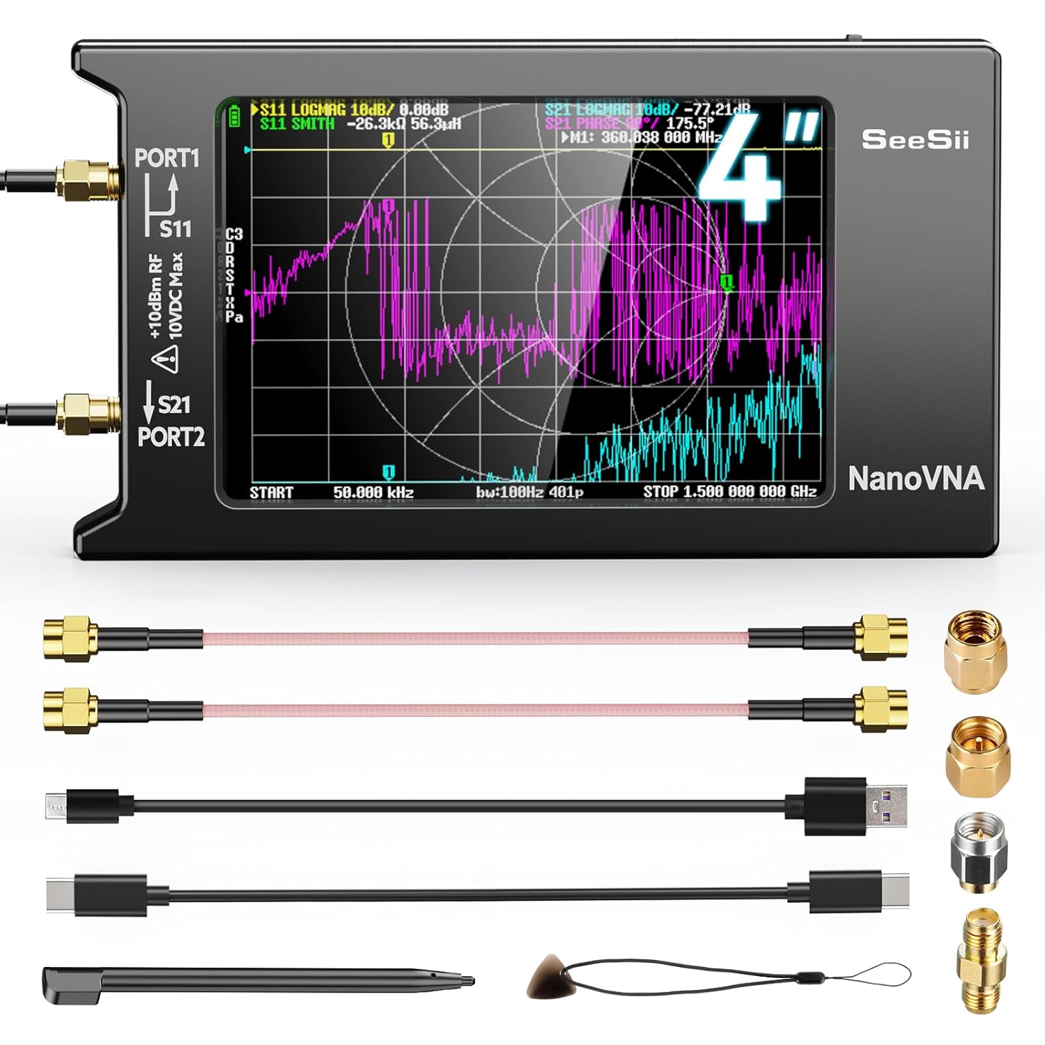
The SeeSii NanoVNA-H4 is a 4-inch vector network analyzer listed for 9 kHz to 1.5 GHz. It measures S parameters, SWR, phase, delay, and Smith-chart information. That makes it relevant when the goal is to examine curve shape and impedance behavior instead of chasing one SWR minimum.
Check On AmazonIf you click this link and buy, we earn a commission at no additional cost to you.
Follow a High-SWR Ham Radio Troubleshooting Order
When the reading is high, begin with the easiest conditions to prove. Confirm the band, frequency, tuner state, antenna switch position, and intended antenna. Then inspect every connector you handled during the test. If a switch, duplexer, lightning protector, or shared feed-line device is in the path, bypass one device at a time with the equipment powered down. A wrong port, damaged switch contact, or partially seated adapter can imitate an antenna fault.
Next, divide the system. Test the radio, patch cable, and inline meter into a suitable dummy load. If that path is normal, reconnect sections of feed line and antenna hardware one at a time when the installation allows it. This prevents antenna trimming from becoming the first response to a damaged connector or wet cable.
| Observation | Likely area to inspect | Next controlled check |
|---|---|---|
| High everywhere, including a dummy load | Meter direction, patch cable, connectors, range setting, or instrument fault | Remove one device at a time and verify with a known-good load |
| High across the band only on the antenna | Open, short, wrong antenna, missing counterpoise, mount reference, or severe mismatch | Inspect continuity only as the antenna design permits, then test at a closer reference plane |
| Dip is below the desired segment | Radiating element may be electrically too long | Confirm the design and installation before making a small reversible adjustment |
| Dip is above the desired segment | Radiating element may be electrically too short | Confirm all added sections, loading, and dimensions before adjustment |
| Reading changes with rain or cable movement | Water intrusion, intermittent connector, damaged coax, or poor strain relief | Stop transmitting and inspect the physical path |
| Reading changes when a door, mast, or nearby object moves | Detuning, coupling, common-mode current, or inadequate mount reference | Restore the normal operating geometry and compare traces |
Coax damage and connector faults deserve their own inspection sequence, covered in checking coax and connector problems. For a wider fault-isolation process when the radio, power, audio, or control system may also be involved, use diagnosing the complete ham station.

This MOOKEERF set contains two 3-foot RG8X jumper cables with PL-259 male connectors and a listed 50-ohm impedance. The listing identifies use with ham radio, SWR meters, and antenna analyzers. A pair of short jumpers is useful when isolating the test path and swapping one known connection at a time during high-SWR troubleshooting.
Check On AmazonIf you click this link and buy, we earn a commission at no additional cost to you.
Apply the Result to the Actual Antenna System
A VHF or UHF home antenna can change noticeably when moved near siding, gutters, attic wiring, a mast, or another antenna. Feed-line loss also becomes increasingly important as frequency rises. If the reading changes after relocation, inspect the physical surroundings and cable route before changing the antenna element.
For those location and height decisions, use setting up a VHF or UHF antenna. With an HF wire, support points, end clearance, feed-point height, nearby conductors, and ground conditions can move the curve, so review planning a beginner HF wire antenna before trimming wire.
Mobile installations add body material, mount bonding, coax routing, hatch movement, and nearby vehicle electronics. A stable reading in the driveway does not prove the cable will remain unpinched or the mount will maintain its RF reference after vibration and weather. Review verifying a mobile antenna installation when the fault appears on a vehicle.
The practical takeaway is to diagnose within the antenna’s real environment. Moving the system to a different location for a test can be useful, but record the change because it may remove the condition that caused the original problem.

Coax-Seal is a moisture-proof sealing tape supplied as four 12-foot rolls in this Pro Pack. The listing describes it for sealing coaxial fittings against moisture, water, and corrosion while remaining flexible. It is relevant to an antenna-system section where weather exposure and water intrusion can change the physical feed-line environment.
Check On AmazonIf you click this link and buy, we earn a commission at no additional cost to you.
A Tuner Can Protect the Radio Without Fixing the Antenna
An antenna tuner transforms the impedance presented to the transmitter. When it finds a match within its range, the radio may see an acceptable load and deliver normal power. That does not mean the feed line has stopped carrying standing waves or that the antenna has become efficient.
A tuner can therefore mask a loose connector, wet feed line, damaged antenna, missing counterpoise, or inappropriate configuration. It may also create high voltage or current inside the tuner or elsewhere in the system when asked to match an extreme load. A successful tune indicator is not a complete safety inspection.
Measure the raw antenna system with the tuner bypassed when the equipment design permits it. Diagnose unexpected changes first, then use the tuner for the mismatch it was intended to handle. If the system previously worked without difficulty and suddenly needs a much wider tuner setting, treat that change as a fault clue.
Field note: I use the tuner after the antenna path makes sense, not as the first troubleshooting step. A tuner is valuable when it is matching a known system; it is misleading when it is hiding an unknown failure.

The GOOZEEZOO V3.2 ATU-100 EXT is an automatic antenna tuner listed for 1.8 to 55 MHz with a 5000mAh battery. It is designed to perform impedance matching for amateur-radio equipment in a compact enclosure. It fits this section as an example of a tuner that can transform the load seen by the transmitter without repairing a faulty antenna or feed line.
Check On AmazonIf you click this link and buy, we earn a commission at no additional cost to you.
Stop the Test When the System Shows Damage
Release PTT immediately if you hear arcing, smell hot insulation, see smoke, feel unexpected heat, observe a rapidly changing reading, or receive a transmitter protection warning. Do not keep applying power to see whether the problem clears. Intermittent faults can become permanent damage under a carrier.
Stop as well when connectors are wet, cable shielding is exposed, a mount is loose, the antenna can contact a person or power line, or the instrument rating is uncertain. Power down and disconnect the station before touching RF connectors. Components can retain heat, and outdoor systems can carry static charge even after transmission ends.
A reading that cannot be repeated under the same conditions is not ready for normal operation. Return to the dummy load, verify the instrument setup, and inspect the physical system. When the fault involves a tower, roof, vehicle safety system, mains power, lightning protection, or inaccessible cable path, hand the work to a qualified installer.
Stop condition: Do not increase power to force a clearer reading. More power increases stress without correcting the cause of a high or unstable SWR result.
Document the Setup Before and After Each Change
A useful SWR record contains enough detail to reproduce the test. Write down the band, exact frequencies, antenna configuration, element dimensions, feed-line type and length, adapters, weather, nearby objects, instrument, power level, tuner state, and calibration plane. Save the analyzer trace when the instrument supports it.
Change one variable at a time. If you shorten an element, move a counterpoise, replace a patch cable, and relocate the antenna before measuring again, you will not know which change moved the curve. Small reversible steps make diagnosis faster and protect an antenna from being cut past the correct length.
- Record the original low, middle, and high frequency readings.
- Photograph connector and mount positions before disassembly.
- Label the test cable and calibration plane.
- Write down the single change made.
- Repeat the same sweep under similar conditions.
- Keep the previous trace as the station baseline.
The baseline becomes especially valuable after a storm, vehicle repair, antenna relocation, or unexplained protection event. Recheck it across major seasonal temperature changes because cable length, supports, ground conditions, and nearby vegetation can shift gradually. You are then comparing the current system with a known working configuration instead of judging one number in isolation.

The Rite in the Rain 935T-KIT combines a 3-by-5-inch top-spiral weatherproof notebook, protective fabric cover, and weatherproof pen. The compact kit keeps field notes and writing gear together during station checks. It is a practical place to record frequencies, antenna configuration, instrument settings, and each single change before repeating the SWR test.
Check On AmazonIf you click this link and buy, we earn a commission at no additional cost to you.
Final Thoughts: Measure First, Then Change One Thing
A useful SWR check should lead to a diagnosis, not just a ratio. Verify the instrument, begin at low power, measure across the intended segment, preserve the reference plane, and compare the result with the exact radio and antenna limits.
I would rather stop and isolate the feed line than trim an antenna in response to one unexplained reading. When the curve is documented and each change is controlled, SWR becomes a practical fault-finding tool instead of a number that sends the operator in circles.
FAQs
📡 What is a good SWR for ham radio?
Use the limits in the transmitter and antenna manuals. There is no universal cutoff because protection thresholds, tuner ranges, antenna bandwidth, and operating conditions differ.
📻 Can I check SWR with the radio’s built-in meter?
Yes, when the radio manual provides an SWR test procedure. Use low power, a brief transmission, and several frequencies across the segment rather than relying on one display reading.
🧪 Is an antenna analyzer safer than transmitting?
It avoids applying normal transmitter power to an unknown load and makes sweeps easier. It still has limits, must be calibrated correctly, and must be disconnected before any transmitter can feed power into it.
🎛️ Should I turn off the antenna tuner before measuring?
Bypass it when you want to measure the raw antenna and feed line and the equipment permits that test. Measure with the tuner engaged only when you are intentionally documenting what the transmitter sees after matching.
📈 Why is SWR low on one frequency but high nearby?
The antenna may have a narrow matched bandwidth or the lowest point may be outside your intended segment. Sweep the range and compare the curve with the antenna design before changing element length.
🌧️ Why does SWR change when it rains?
Moisture can change the antenna environment or enter a connector and feed line. A large or persistent change is a reason to inspect weather sealing and cable condition before transmitting normally.
🔌 Can a bad coax connector cause high SWR?
Yes. A loose, shorted, open, corroded, wet, or poorly installed connector can create a high or unstable reading. Isolate the system with a suitable dummy load and known-good patch cable before adjusting the antenna.
🛑 What should I do if the SWR reading keeps moving?
Stop transmitting and inspect for intermittent connectors, cable movement, water, arcing, heat, or nearby objects changing position. Do not increase power or use the tuner to hide an unstable fault.