
A useful antenna setup starts with the operating job, the property, and a safe feedline path, not with the largest gain number in a listing. Home VHF/UHF, a first HF wire, restricted housing, and a vehicle each create a different installation problem. This guide helps you choose the correct path, recognize the limits that change the answer, and know when to stop and hand the work to a qualified professional. It does not rank antenna models or replace a full review of SWR, grounding, lightning protection, and RF exposure.

Start With the Band and the Operating Job
A practical ham radio antenna setup begins by naming what the station must do. Local VHF/UHF repeater work, VHF/UHF simplex, regional HF contacts, longer-distance HF operating, temporary portable use, and mobile operation do not reward the same antenna location or feedline plan. Choosing an antenna type before choosing the job often creates a system that can be installed but does not solve the operator’s actual problem.
The first question is not, “How much gain can I buy?” It is, “Where must the signal go, on which band, from what physical location?” At VHF and UHF, antenna height, surrounding terrain, buildings, and feedline loss can matter more than a gain figure taken out of context. On HF, available wire length, support points, feed-point location, common-mode control, and the bands you intend to use shape the decision before a tuner enters the conversation.
Field Note: I have seen home antenna plans stop after the operator discovers an HOA restriction late in the process. The useful lesson is not to hide the antenna better. It is to check property rules, support locations, cable entry, and safety before buying hardware or committing to one design.
This article keeps the choice at the navigation level. The detailed station sequence, from radio placement through the antenna system, is covered in planning a complete ham radio setup. Here, the goal is to put you on the correct installation path before details from one situation are mistakenly applied to another.
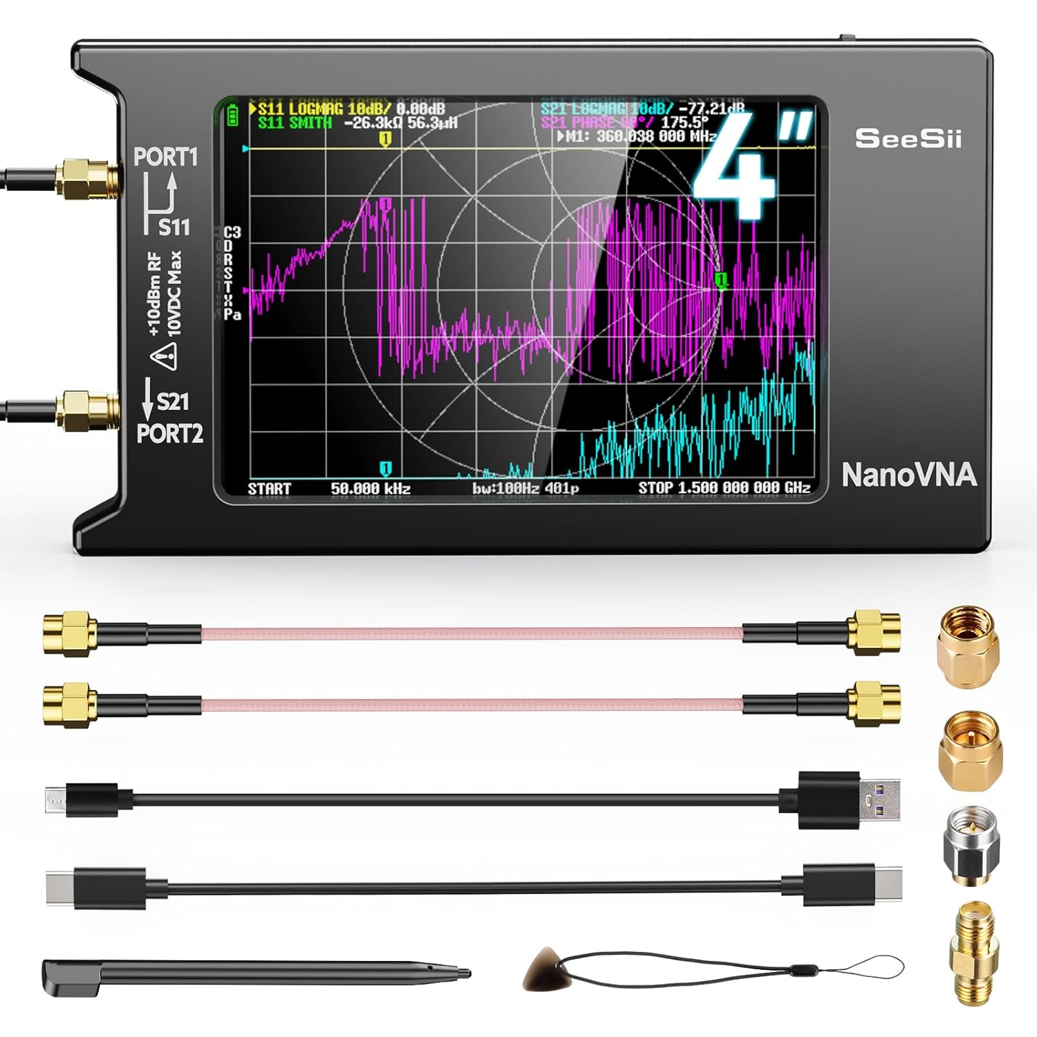
This compact vector network analyzer covers 9 kHz to 1.5 GHz and uses a 4.0-inch LCD touchscreen. It can evaluate antenna resonance and SWR across a broad frequency range. Its measurement range supports the band-specific antenna checks discussed in this section.
Check On AmazonIf you click this link and buy, we earn a commission at no additional cost to you.
Use a Four-Path Decision Map Before You Install Anything
No single antenna design fits every new operator. The useful choice is the one that matches the band, property, support points, cable route, access restrictions, and safe separation from people and utilities. A simple decision map prevents the common mistake of treating every installation as a shopping problem.
| Your operating situation | Primary installation question | What usually decides the path |
|---|---|---|
| Home VHF/UHF | Do you need broad local coverage or one preferred direction? | Safe height, clear surroundings, support, feedline length, and repeater or simplex direction |
| First HF wire | Which bands can your available wire space and support points serve? | Wire geometry, feed-point access, common-mode control, nearby objects, and tuner requirements |
| Apartment or HOA property | What does the lease, private covenant, and local zoning actually allow? | Written permission, balcony or attic access, indoor noise, RF separation, and portable alternatives |
| Vehicle | Where can the antenna and coax be placed without compromising safety or vehicle systems? | Body material, mount location, cable route, clearance, bonding, weather sealing, and verification |
The table is not a substitute for inspecting the site. Its purpose is to tell you which facts to collect before choosing a design. If you cannot identify a legal location, a safe support, a reasonable cable route, and a way to verify the finished system, the project is not ready for permanent installation.
- Write down the bands and the contacts you want to make.
- Mark possible antenna, support, and feed-point locations.
- Measure the likely feedline route rather than guessing from room-to-room distance.
- Check lease, covenant, zoning, permit, and vehicle restrictions before drilling or mounting.
- Pass the safety gate before testing or making the installation permanent.
This sequence separates a reversible test from a committed installation. A temporary, safely supported trial can reveal noise, pattern, clearance, and cable-routing problems before holes, roof work, or permanent hardware make the correction expensive.
Choose the Home VHF/UHF Path by Direction and Height
A ham radio home antenna setup for local FM use usually starts with an external vertical or a directional antenna, but those choices solve different problems. A vertical supports contacts in many directions and is often the simpler match for several local repeaters. A directional antenna can favor one area and reject some signals from other directions, but it may become inconvenient when the stations you want are spread around the compass.
Height is valuable at VHF and UHF because buildings, terrain, trees, and the local radio horizon shape the path. That does not justify placing an antenna on an unsafe roof edge or near overhead conductors. A lower safe location that can be maintained and fed correctly is a better starting point than an ambitious support that requires unsafe access or has not been checked for structural loading.
Feedline deserves equal attention. Loss depends on cable type, length, frequency, connectors, and installation quality, so a long run that seems harmless on HF may consume a meaningful part of a VHF/UHF signal. The answer is not always the thickest cable available, because bend radius, connector fit, weather entry, support, and the path into the operating position still have to work as one system.
Do not promise yourself a fixed number of miles from a gain figure. Before making the installation permanent, confirm the intended repeater or simplex direction, listen from the proposed location, verify the antenna system with suitable test equipment, and note whether nearby structures create an obvious blockage. The detailed path for support, feedline, orientation, and practical verification is covered in the home VHF/UHF guide listed after the final section.

The SW-102 is a digital antenna power and SWR meter covering 125 to 525 MHz. It is designed for VHF and UHF measurements, matching this section's focus on verifying a home antenna system on those bands. It supports checking the installed system instead of relying on a gain figure alone.
Check On AmazonIf you click this link and buy, we earn a commission at no additional cost to you.
Fit the First HF Wire to the Property, Not the Diagram
Your first ham radio antenna for HF may be a dipole, an inverted V, or an end-fed system, but the familiar name does not make the installation interchangeable. A dipole needs two useful directions from its feed point. An inverted V can reduce the number or spacing of supports, while an end-fed arrangement moves the feed point to one end and changes the way feedline current, matching, and common-mode control must be handled.
Start with the bands you expect to use, then map the wire space and support points that actually exist. Check where the feed point can be reached, how the feedline will leave the antenna, how close the wire may come to buildings and people, and whether the support can handle wind and weather. Trees move, branches fall, and improvised supports can load wire and hardware in ways that are not obvious on a calm afternoon.
A tuner is not permission to ignore the antenna system. It may help the transmitter see an acceptable impedance within its operating range, but it does not remove feedline loss, common-mode current, poor placement, unsafe voltage points, or a wire that is unsuitable for the intended bands. Treat matching, choking, feedline choice, and antenna geometry as connected decisions rather than separate accessories added after the problem appears.
The practical comparison is not which wire type wins in every yard. It is which arrangement fits your support points, feed-point access, band goals, and ability to control current on the outside of the feedline. The detailed beginner HF wire path is linked in the installation guides near the end of this article, where the design choices can be handled without turning this overview into an advanced antenna-engineering lesson.

This end-fed half-wave antenna is listed for the 10, 12, 15, 17, 20, 30, 40, and 80 meter amateur bands. It uses a 1:64 balun and is the 150-watt model. As an end-fed configuration, it directly matches one of the HF wire layouts this section asks operators to fit to their actual support points and feed-point access.
Check On AmazonIf you click this link and buy, we earn a commission at no additional cost to you.
Separate Lease, HOA, and Zoning Restrictions
Restricted housing is not one legal category. A lease is a private agreement with a landlord, an HOA covenant or CC&R is a private property restriction, and a zoning rule comes from a state or local government. PRB-1 addresses state and local land-use regulation, but it does not automatically override private HOA covenants, CC&Rs, or rental agreements.
That distinction changes the next step. For a rental or HOA property, read the controlling document and seek written approval before attaching hardware, routing cable through common areas, drilling, or creating an exterior change. For a zoning or permit question, check the current local process rather than assuming federal amateur-radio policy eliminates height, safety, appearance, setback, or permit requirements.
Balcony, indoor, attic, portable, and vehicle options each trade one problem for another. A balcony may have metal railings, limited clearance, falling-object risk, and rules about anything extending beyond the space. An attic avoids exterior visibility but can add building-material loss, household noise, heat, access difficulty, and RF-exposure questions when the antenna is near occupied rooms.
Warning: Do not conceal an installation from a landlord, association, or property manager when approval is required. Stop if the route crosses a shared wall, roof, exterior envelope, fire barrier, or common space without clear authorization. A portable or vehicle setup can be a lawful bridge while you work within the property rules, but it should not be used to bypass them.
The correct restricted-housing solution is the one that remains legal, safe, removable when required, and usable on the bands that matter to you. The apartment and HOA guide listed later focuses on those trade-offs without pretending that one stealth method is acceptable for every property.
Treat the Mobile Antenna as Part of the Vehicle
An amateur radio antenna installation on a vehicle must fit the vehicle’s structure and safety systems, not just the radio connector. Mount location affects pattern, clearance, mechanical load, and the path the coax must take. A central, unobstructed location often supports a more even pattern, but the correct location still depends on roof material, body construction, antenna size, garage clearance, and whether permanent modification is allowed.
Vehicle material matters because an antenna system that expects a conductive body or ground plane may behave differently on steel, aluminum, fiberglass, composite panels, or a glass roof. Bonding can also become part of the system, especially when body panels, hinges, exhaust components, or other sections do not provide the RF connection the installation expects. These are reasons to inspect and verify, not reasons to apply one bonding recipe to every vehicle.
Coax routing is a safety decision. Keep it away from pedals, steering components, seat tracks, sharp metal, hot areas, weather paths, airbag deployment zones, and unknown factory wiring. Do not drill, remove trim, or pass cable through a firewall unless you know what is behind the surface and can preserve the vehicle’s seals and safety systems.
Warning: Stop and use a qualified mobile installer when the proposed route approaches airbags, restraint wiring, high-voltage hybrid or electric-vehicle components, fuel-system areas, or concealed factory harnesses. Also stop if the antenna cannot clear garages, branches, parking structures, or other routine obstacles without creating a mechanical hazard.
A mobile installation is complete only after the mount is mechanically secure, the coax is protected, clearance has been checked through normal vehicle use, and the antenna system has been verified on the intended bands. The dedicated mobile guide listed below handles that path without assuming that one mount or one body style works everywhere.

This mobile antenna mount kit combines a stainless steel L-bracket with an NMO base and a PL259-ended coax run. The included RG58 coax is 13 feet long for routing from the antenna mount toward the radio. It fits this section's emphasis on treating mount location and coax routing as connected vehicle-installation decisions.
Check On AmazonIf you click this link and buy, we earn a commission at no additional cost to you.
Pass the Safety Gate Before Testing or Transmitting
Safety is not the last inspection after the antenna is in place. It is a gate that can stop the project before roof access, mast work, drilling, or transmission begins. If the site cannot pass that gate, choose a different location, reduce the scope, use a temporary safe alternative, or bring in a qualified professional.
- Overhead power lines: Do not install, raise, lower, carry, or retrieve an antenna, mast, ladder, wire, or tool where it could contact an overhead conductor. If a support or wire can fall into the line, the location is not acceptable.
- Roof and ladder work: Stop if the surface is wet, windy, icy, steep, fragile, or beyond your fall-protection ability. Do not improvise roof access or work alone where a fall or dropped object could injure someone.
- Structural loading: A roof edge, chimney, railing, tree, mast, and wall bracket are not automatically suitable supports. Wind area, leverage, fasteners, corrosion, and the supporting structure require a site-specific judgment.
- Weather and lightning: Do not work on an antenna during a storm or when lightning is possible. A disconnected feedline is not a complete lightning-protection design.
- RF exposure: Complete the required station evaluation using the actual frequency, power, duty cycle, antenna gain, pattern, and distance to people. Reassess when a change can alter exposure.
- Permits and codes: Check current local building, electrical, zoning, and vehicle requirements. Use a licensed electrician, qualified installer, engineer, or other appropriate professional where the work or local code requires one.
These stop conditions are deliberately conservative because the consequences are not limited to a weak signal. Power-line contact, falls, structural failure, water entry, vehicle-system damage, lightning current, and excessive RF exposure are not problems to solve by trial and error. No contact is worth creating a hazard for the operator, household, neighbors, or public.
Current FCC RF-exposure rules require amateur stations to be evaluated for compliance. An evaluation may show that a station is exempt from more detailed analysis or already meets the applicable limits, but the operator still needs to make that determination from the real installation. Keep the calculation and assumptions with the station information, then repeat the review when power, antenna, location, gain, or operating pattern changes in a way that can affect exposure.
Hand the Antenna Off to the Rest of the Station System
The antenna choice is not finished when the radiator is mounted. Feedline loss, connectors, weather entry, SWR measurement, grounding and bonding, lightning planning, and RF assessment determine whether the installed system is usable and safe. Those topics interact, but each requires more depth than a navigation article can provide responsibly.
Coax selection must use the actual frequency, length, routing space, connector plan, outdoor exposure, and acceptable loss. SWR must be measured in a way that matches the antenna and feedline arrangement, then interpreted as a diagnostic clue rather than a complete score for antenna performance. A low reading does not prove that the antenna radiates efficiently, has the intended pattern, or is safe.
Grounding, bonding, and lightning protection are also different jobs. An RF-current problem, an electrical-safety connection, and a lightning-protection path may involve related conductors, but they are not interchangeable labels for one wire attached wherever space remains. The site, electrical service, feedline entry, local code, and existing grounding electrode system determine when a licensed electrician or qualified lightning-protection professional must take over.
Use the station basics and safety path for coax, SWR, grounding, lightning, and RF-exposure planning. That handoff keeps this article focused on choosing the correct installation route while giving the safety-critical parts the space they require.

This black self-fusing silicone tape is 1.5 inches wide, 15 feet long, and 30 mil thick. It is sold for weatherproof sealing around outdoor antenna coax and electrical cables. It supports this section's weather-entry planning without being presented as a substitute for grounding or lightning protection.
Check On AmazonIf you click this link and buy, we earn a commission at no additional cost to you.
Final Thoughts: Choose the Installation Path Before the Antenna
Antenna type matters, but location, height, feedline, supports, surroundings, property rules, and safety decide whether that type can work in your situation. Start with the band and operating goal, draw the physical route, check the legal limits, and apply the safety gate before choosing a permanent design. That order prevents a gain number or familiar antenna name from overruling the facts of the site.
The next move is to choose one of the four installation paths below. Read the guide that matches the place where you will operate, then move into the station-safety material before drilling, climbing, grounding, or transmitting. A modest installation that is legal, maintainable, tested, and safe is more useful than an ambitious system that cannot be completed responsibly.
Choose Your Antenna Installation Guide
Each location creates a different set of decisions. Use the guide that matches your operating site so the advice stays specific to the supports, restrictions, feedline route, and verification work you will face.
| Installation guide | What it helps you decide |
|---|---|
| Home VHF/UHF Antenna Setup | Choose between broad and directional coverage while planning safe height, support, feedline, and local path limits. |
| First HF Wire Antenna | Match a dipole, inverted V, or end-fed arrangement to bands, available space, support points, and feed-point access. |
| Apartment and HOA Antenna Options | Separate lease, covenant, and zoning limits before comparing balcony, attic, indoor, portable, and vehicle paths. |
| Mobile Antenna Installation | Plan mount location, vehicle compatibility, coax routing, bonding, clearance, and final system verification. |
Once the location-specific choice is clear, return to the whole station system and complete the feedline, measurement, grounding, lightning, and RF-safety work before regular operation.
FAQs
📡 What is the best first ham radio antenna?
There is no single best design for every beginner. Choose by band, operating goal, property, support points, feedline route, restrictions, and safe distance from people and utilities.
🏠 Is an outdoor antenna always better than an indoor antenna?
An outdoor location often avoids some building loss and indoor noise, but it also adds weather, support, lightning, permit, and access concerns. An indoor or attic antenna may be the correct compromise when it is legal, safely separated from people, and evaluated for RF exposure.
📏 How far will a home VHF/UHF antenna reach?
A fixed mileage claim is not reliable without the antenna height, terrain, buildings, feedline loss, power, repeater location, and receiver conditions. Plan around the specific path you need, then test and verify from the proposed location.
🌳 Can I use a tree to support an HF wire antenna?
A tree may be usable only when the wire, support method, movement, falling branches, access, and distance from power lines can be managed safely. Do not climb, throw lines, or place wire where any part could contact an electrical conductor.
🏢 Does PRB-1 override my HOA or apartment lease?
No. PRB-1 concerns state and local land-use regulation and does not automatically preempt private HOA covenants, CC&Rs, or rental agreements. Check the controlling documents and any current state protections before installing anything.
🚗 Can I route mobile coax through a door or window seal?
Only when the cable will not be crushed, cut, repeatedly flexed, or used as a water path. Stop and use a qualified installer if the route approaches airbags, restraint wiring, high-voltage systems, concealed harnesses, or a required vehicle seal.
⚡ Do I need an RF-exposure evaluation for a new antenna?
Current FCC rules require amateur stations to be evaluated for RF-exposure compliance. Use the real frequency, power, duty cycle, gain, pattern, and distance to people, then reassess when a station change can alter exposure.
🛠️ Does low SWR mean the antenna installation is good?
No. Low SWR shows an impedance relationship at the measurement point, but it does not prove efficient radiation, the intended pattern, low feedline loss, safe RF exposure, or adequate lightning protection.