Ham radio grounding and lightning protection are not one job solved by running a wire from the radio to a ground rod. AC electrical safety, equipment bonding, RF-current control, and lightning or surge protection solve different problems, and a connection that helps one function may do little for another. A safe station plan identifies the function first, routes every conductor through a controlled entry strategy, and keeps any required electrodes bonded into the building grounding system under current local code. Building-entry work, grounding-electrode changes, rooftop systems, towers, and lightning design require review by qualified local professionals.

Grounding Is Four Separate Functions
The most common planning mistake is treating every use of the word ground as if it meant the same electrical path. A green safety conductor in an outlet, a short bond between equipment chassis, a feedline choke, and an exterior surge-protection connection do not perform interchangeable jobs. Connecting all four ideas to a random rod does not create a complete protection system. It can instead add unwanted current paths or hazardous voltage differences.
I start a station review by labeling the problem before looking at hardware. Is the concern shock protection from an AC fault, voltage difference between connected equipment, RF current on the outside of a feedline, or energy entering from an outdoor conductor? That first decision prevents the operator from buying a lightning protector to cure RF in a microphone or adding an RF wire to solve a damaged outlet ground.
| Function | Problem it addresses | First planning question |
|---|---|---|
| Electrical safety | Fault current, shock, and exposed conductive parts becoming energized | Is the station powered through approved wiring with an intact protective conductor? |
| Equipment bonding | Unwanted voltage differences between connected conductive parts | Which chassis, panels, and entry conductors must be interconnected? |
| RF-current control | Common-mode current, RF feedback, and feedline radiation | Where is RF current flowing outside its intended antenna path? |
| Lightning and surge protection | Transient energy entering through outdoor antenna, control, or power conductors | Where do conductors enter, and how are protective devices bonded to the building system? |
This function-first framework is the foundation for a practical home station. It also explains why a complete ham radio station planning process should identify power, antenna entry, equipment location, and building constraints before the desk is filled with equipment.

This second edition separates AC safety, lightning protection, and RF management instead of treating grounding as one job. It covers station environments ranging from home and apartment installations to portable operation and outdoor antennas. It is a useful reference for identifying the function first before choosing grounding, bonding, or protection hardware.
Check On AmazonIf you click this link and buy, we earn a commission at no additional cost to you.
Function 1: Electrical Safety and Fault Clearing
The protective conductor in a correctly installed AC system provides a fault-clearing path when damaged insulation or wiring energizes an equipment chassis. That path is part of the building electrical system, not an optional radio accessory. The station should use approved outlets, intact cords, correctly rated distribution equipment, and the grounding method required by the equipment instructions and locally adopted electrical code.
Never defeat a three-wire plug, remove a protective conductor, use an adapter to hide a missing equipment ground, or treat a separate outdoor rod as a replacement for faulty branch-circuit wiring. A rod in soil may not provide the low-impedance fault path needed for an overcurrent device to operate promptly. If a receptacle tests incorrectly, a chassis produces a shock or persistent tingle, a plug becomes hot, or wiring condition is uncertain, stop using the station and have the electrical system inspected.
Stop condition: Do not open service equipment, alter mains wiring, install a surge device in a panel, or attempt to repair a questionable protective-earth connection unless you are qualified and permitted to perform that work. A licensed electrician should handle conditions involving the service panel, branch circuits, damaged outlets, unknown legacy wiring, or repeated breaker and GFCI trips.
A station ground terminal on the back of a radio does not override the power-supply manual or building wiring requirements. It may be part of a bonding or RF-management plan, but it is not permission to bypass the safety conductor already provided through the AC system. Electrical safety must work with the radio disconnected from every antenna, tuner, and accessory.

The RT250 is made for standard 3-wire 120V receptacles and adds an LCD readout to outlet testing. Its GFCI test function helps check GFCI receptacle operation without opening electrical equipment. It is useful for identifying receptacle conditions that should be addressed before radio equipment is connected.
Check On AmazonIf you click this link and buy, we earn a commission at no additional cost to you.
Function 2: Bonding Connected Equipment
Bonding means intentionally interconnecting conductive parts so their voltage difference remains controlled for the function being addressed. In a station, that may involve radio chassis, power supplies, amplifier enclosures, antenna switching equipment, entry panels, and protective devices. The required route, material, and connection method depend on frequency, fault current, surge current, equipment design, and code.
Short and direct interconnections are usually easier to control than long loops routed around a room. Long conductors have inductance and can develop significant voltage during a fast transient or behave as part of an RF circuit. That is why a neat daisy chain from one chassis to the next is not automatically equivalent to a planned bonding layout.
Field Note: When I review a bonding plan, I draw every conductive path, including coax shields, USB cables, control leads, power-supply negative conductors, and protective conductors. The path that was not drawn is often the path that explains why two boxes do not remain at the same potential.
Bonding should not be improvised by clipping equipment to a radiator, water pipe, balcony rail, outlet cover screw, or unidentified building steel. Those objects may be discontinuous, isolated by plastic sections, shared with other systems, or prohibited for the intended purpose. When the bond involves an exterior entry, grounding electrode, tower, rooftop structure, or building metal, the design belongs in a local code review rather than a generic online diagram.

This 15-foot tinned copper braided sleeve is 1/2 inch wide and is sold for shielding and ground-strap applications. The flexible braid suits short equipment-bonding runs when the station design calls for them. Use it only as part of a reviewed bonding plan because it is not a substitute for the building protective conductor or grounding-electrode system.
Check On AmazonIf you click this link and buy, we earn a commission at no additional cost to you.
Function 3: RF-Current Control
RF problems occur when current travels on paths the antenna system was not intended to use. Common-mode current can flow on the outside of coax, along control cables, through computer connections, across equipment cases, or into AC wiring. The symptoms may include RF in transmitted audio, unstable computer interfaces, a hot microphone or key, changes when a cable is touched, interference to nearby electronics, or an antenna pattern that changes with feedline routing.
An arbitrary long wire from the desk to a rod can make this worse. At radio frequencies, a conductor that looks like a ground at DC may have substantial impedance and may radiate as part of the antenna. The better question is where the common-mode current begins and which path is allowing it to reach the station.
- Check antenna balance: Confirm that the antenna and feed arrangement match the intended design.
- Inspect feedline routing: Look for coax running close to station wiring, computer cables, or other conductors that can couple RF.
- Use an appropriate choke where justified: Choose its location and frequency coverage for the actual common-mode path rather than treating any coil of coax as universal.
- Separate signal and power paths: Reduce large loops and avoid routing sensitive leads beside high-RF-current conductors.
- Test one change at a time: Record power, band, antenna, cable layout, and the symptom before deciding that the problem is solved.
A feedline choke, equipment bond, and antenna counterpoise can all be useful, but they solve different parts of the RF circuit. The detailed choice depends on the antenna and band. Review the coax and connector signal path before assuming that a ground wire is the missing component.
RF symptoms also need to be separated from electrical faults and exposure concerns. A tingling case may be RF, leakage, or a wiring defect, and guessing is not a safe diagnostic method. Use the structured ham radio troubleshooting process to isolate the symptom, and confirm the station through an appropriate RF exposure safety evaluation rather than treating grounding as a substitute for distance and power controls.

This four-pack uses snap-on ferrite cores intended to suppress EMI on cables without cutting the cable. The clamp-on format makes it practical to try different cable locations while troubleshooting unwanted RF paths. Treat it as a troubleshooting component, not a universal choke, and confirm that its impedance behavior is appropriate for the actual band and cable involved.
Check On AmazonIf you click this link and buy, we earn a commission at no additional cost to you.
Function 4: Lightning and Surge Protection
Outdoor conductors create a route for lightning energy and induced surges to approach the building. Coax, antenna-control cable, rotor wiring, network cable, receive lines, and power conductors all need to be considered. Protecting only the coax while allowing an unprotected control cable to enter beside it leaves another conductive path into the station.
A lightning-protection plan normally begins at the building entry, not behind the radio. Protective devices must be listed or approved for their intended application, compatible with the connector and frequency range, installed according to their instructions, and bonded through an appropriate route to the building grounding electrode system as required by adopted code. The conductor route matters because long loops, sharp routing, poor connections, and isolated electrodes can produce large voltage differences during a transient.
No protector makes it safe to operate during a thunderstorm, and no component can promise that equipment will survive a direct strike. Protection is a layered risk-reduction system that may include the antenna structure, entry panel, bonding, surge devices on every incoming service, internal coordination, weatherproofing, and a disconnect strategy prepared before bad weather. The design must also account for the building electrical service, because surge energy can enter through more than the antenna.
Professional review required: Do not copy a ground-rod count, conductor size, entry-panel diagram, or protector layout from another station without a site review. Soil, electrode system, service location, conductor length, building material, tower design, local amendments, and inspection requirements can change the correct solution.
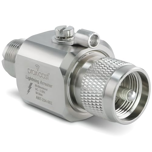
This 50-ohm coaxial protector uses UHF male and female connectors and is specified from 0 to 3 GHz. It uses a replaceable 230V gas-discharge tube and is rated for up to 200W input. It belongs at a properly designed, bonded entry point and does not make a station safe to operate during a thunderstorm.
Check On AmazonIf you click this link and buy, we earn a commission at no additional cost to you.
Use a Planned Single-Point Entry Concept
A single-point entry concept brings outdoor radio conductors through one controlled area so protectors and cable shields can be bonded consistently before the conductors continue toward the equipment. The goal is not a magical plate that eliminates every surge. It is to avoid scattered entry paths that let one cable rise to a different potential from another cable connected to the same radio.
The entry plan should account for coax, control lines, network links, remote antenna switches, rotor cable, and any other conductor that crosses from outside to inside. Power and communication protectors have different requirements and cannot be substituted for one another. Every protective device must be accessible for inspection, protected from weather as required, and installed with the conductor routing specified by its instructions and local code.
The coax route should also preserve weather sealing, connector strain relief, bend limits, and service access. Those details affect both reliability and whether a later inspection can find corrosion or damage. The broader ham radio antenna setup process should treat the entry point as part of the antenna system rather than an afterthought at the shack wall.
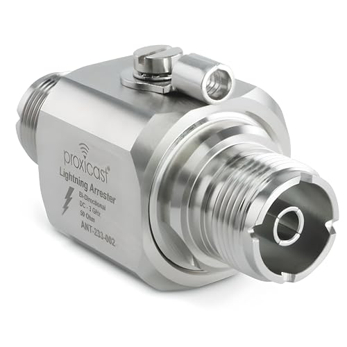
This 50-ohm protector uses two SO-239 female ports, a 230V gas-discharge tube, and a ground lug. It is specified from 0 to 3 GHz with less than 0.2 dB insertion loss and up to 200W input. The dual-female format can fit a planned coax entry panel when the device and bonding route are selected for the site.
Check On AmazonIf you click this link and buy, we earn a commission at no additional cost to you.
Why an Isolated Ground Rod Can Be Hazardous
Adding a rod outside the shack may feel like creating a direct route to earth, but a separate unbonded electrode can rise to a different potential from the building electrical grounding system during a fault or lightning event. Equipment connected to both systems through coax, power wiring, USB cables, or other conductors can then bridge that voltage difference. The station operator may unintentionally place sensitive equipment and people in the current path.
For that reason, the question is not simply whether a rod exists. The questions are whether the electrode is permitted, how it is incorporated into the building grounding electrode system, what conductor and route are required, and which authority has jurisdiction over the installation. Those answers vary with the building and adopted code.
A station owner should not drive a new rod, alter an existing electrode conductor, connect to the service grounding system, or bond to a buried metal system based only on a drawing from another property. Underground utilities, service conductors, plumbing, structural steel, concrete-encased electrodes, and existing lightning systems may all affect the design. Ground disturbance also requires utility locating and property authorization before any work begins.
Key point: More rods do not automatically mean more safety. A code-compliant interconnected system is the objective, while isolated electrodes and uncontrolled parallel paths can create the hazard the operator was trying to prevent.

This illustrated guide focuses on bonding and grounding requirements in the 2023 NEC. It is a useful reference for understanding why grounding electrodes and bonding paths are part of a coordinated electrical system rather than isolated radio add-ons. For a station owner, it supports informed questions before electrode or service-ground work is handed to a qualified local professional.
Check On AmazonIf you click this link and buy, we earn a commission at no additional cost to you.
Apartment and Portable Stations Have Different Boundaries
An apartment operator may have no legal access to the building grounding electrode system, exterior wall, roof, common balcony structure, or electrical service. That does not mean the operator should invent a substitute connection. Plumbing, outlet screws, balcony rails, fire escapes, and building steel may be unsafe, prohibited, electrically discontinuous, or part of systems the tenant is not authorized to modify.
Many indoor or temporary stations do not require a separate RF ground wire. A balanced or otherwise complete antenna system with controlled common-mode current may operate correctly without one. The operator still needs intact AC safety wiring, an appropriate antenna location, RF exposure compliance, and a plan that does not route conductors into unsafe exterior spaces.
Portable operation has another set of conditions. A battery-powered station with no building connection does not copy the grounding design of a permanent home station, while a generator, shore-power connection, metal shelter, temporary mast, or long outdoor feedline can introduce additional electrical and lightning concerns. The power source and site rules determine what safety measures apply.
Do not improvise: Never attach antennas or conductors near overhead power lines, and do not use plumbing or unidentified building metal as a convenient ground. Obtain property permission and qualified advice before modifying a rental, shared structure, rooftop, balcony, or electrical system.

This rechargeable LiFePO4 pack is rated at 12.8V, 6Ah, and 76.8Wh. Its compact battery format can support portable 12V-class equipment when the load, connector, and current requirements are compatible. A battery-powered station changes the power boundary, but it does not remove antenna, lightning, or RF-exposure considerations.
Check On AmazonIf you click this link and buy, we earn a commission at no additional cost to you.
Inspect the System, Not Just the Radio
A protection plan changes as weather, corrosion, renovations, and equipment changes alter the station. Outdoor connectors can admit moisture, bonding surfaces can oxidize, fasteners can loosen, protectors can be damaged by a transient, and conductor jackets can be cut by movement or sunlight. A system that passed inspection when installed should not be assumed correct forever.
Inspection should follow the equipment instructions, the professional design, and local maintenance requirements. Do not open a protector, panel, service enclosure, or energized equipment to inspect internal parts unless the manufacturer allows it and you are qualified to do so. Visual checks should stop when they reveal heat damage, cracking, water entry, severe corrosion, loose structural hardware, or any condition requiring disassembly near mains or outdoor hazards.
- Entry area: Look for water paths, failed seals, damaged enclosures, loose cable support, and new conductors that bypass the planned entry.
- Accessible bonds: Check for corrosion, mechanical damage, looseness, and incompatible metals according to the installation specification.
- Coax and control cable: Inspect exposed jacket, connector strain, abrasion, animal damage, and sharp bends.
- Protective devices: Follow the manufacturer’s inspection or replacement guidance after a known surge or when condition indicators change.
- Building changes: Reassess the station after service upgrades, solar installation, generator work, remodeling, new antennas, or changes to the grounding electrode system.
Keep a dated diagram and photographs of the cable entry, bonding routes, labels, and professional recommendations. Documentation makes it easier to see what changed and prevents a future repair from silently bypassing a protective path. It also gives an electrician or lightning-protection professional a more accurate starting point than a verbal description from behind the radio desk.

This Coax-Seal Pro Pack provides a 1/2-inch-wide, 12-foot roll of moisture-proof sealing tape. The material is made to wrap connections and fittings to help keep moisture away from outdoor cable interfaces. It is a practical maintenance item for weatherproofing accessible coax connections after inspection finds aging seals or exposed connector areas.
Check On AmazonIf you click this link and buy, we earn a commission at no additional cost to you.
Make the Storm Procedure Before the Storm
A surge protector does not make transmitting during nearby lightning safe. The station should be shut down according to a plan created before thunder is heard, and any optional disconnection should be completed well before the storm reaches the area. Once a thunderstorm is nearby, do not touch feedlines, ground conductors, protectors, electrical cords, plumbing, or equipment connected to outside conductors.
The disconnect plan should state where each outside line goes after disconnection, how exposed connector ends are secured, and whether the planned condition creates a safe separation under the professional design. Simply unscrewing coax from the radio and leaving it on the desk can bring the outside conductor directly into the occupied room. An external disconnect arrangement may reduce that issue, but its location, clearance, weather protection, and bonding need to be designed for the site.
Weather awareness is part of the system. Monitor forecasts before operating, postpone antenna work when thunderstorms are possible, and move indoors before conditions become threatening. Do not climb, lower masts, handle antenna wire, unplug equipment, or make emergency grounding changes after thunder begins.
During nearby lightning: Leave the radio system alone. Move to a safe indoor location, avoid contact with electrical equipment and conductors, and wait until the storm has clearly passed before inspecting or reconnecting the station.

The ER310 receives AM, FM, and NOAA weather channels and includes NOAA Weather Scan plus alert functions for severe-weather notices. It can recharge from its solar panel, hand crank, or rechargeable battery. Keeping an independent weather receiver available supports checking conditions before antenna work or operating decisions, rather than reacting after thunder is already nearby.
Check On AmazonIf you click this link and buy, we earn a commission at no additional cost to you.
Know When the Plan Requires a Professional
Some station decisions can be planned by the operator, such as documenting equipment, identifying every incoming conductor, recording symptoms, and choosing a station location that allows a reasonable cable path. Other decisions affect the building electrical system, structural loading, lightning current, roof integrity, underground utilities, or code compliance. Those decisions require local qualifications and site knowledge.
Bring in a licensed electrician when the work involves service equipment, branch circuits, receptacle grounding, panel-mounted surge protection, grounding-electrode conductors, generator connections, or uncertain building wiring. Use a qualified lightning-protection or communications-grounding professional for a permanent outdoor antenna entry, tower, rooftop system, extensive grounding network, or a property with an existing lightning-protection system. Structural and roofing professionals may also be needed when mounts penetrate or load the building.
The handoff should include a station diagram, equipment manuals, antenna and feedline routes, entry locations, building-service location, known electrodes, and every power or communication service entering the property. Ask for the design to be checked against the currently adopted electrical and building codes, equipment listing instructions, and local inspection requirements. Do not ask a professional to approve a rod or conductor that has already been installed without authorization and utility locating.
A good professional review does not remove the operator from the process. It defines which work is permitted, how the radio system joins the building safely, what must remain accessible, and which conditions require shutdown or reinspection. That is far more useful than a universal diagram that cannot see the house.

The PT-D210 is a monochrome label maker with one-touch formatting controls and 27 built-in templates. It can print up to two lines on labels up to 12 millimeters wide, with multiple fonts, frames, and symbols available. Clear labels help a professional match the station diagram to physical cables, entry paths, and equipment during a grounding or lightning-protection review.
Check On AmazonIf you click this link and buy, we earn a commission at no additional cost to you.
Final Thoughts: Name the Function Before Adding a Wire
Grounding myths persist because several different systems share the same word. Electrical safety clears faults, bonding controls voltage differences, RF management keeps current on the intended path, and lightning protection manages outdoor conductors and transient energy. A station becomes safer when those functions are coordinated, not when every available metal object is connected together without a plan.
Start with a complete drawing of power, equipment, feedlines, control cables, entry points, and the building grounding system. Stop immediately when the work reaches mains wiring, electrodes, rooftops, towers, structural penetrations, overhead power lines, or lightning design. The correct goal is not to claim that the station is lightning-proof. It is to build a code-compliant, inspectable system with clear limits and a storm procedure prepared before it is needed.

This kit combines a weatherproof 4.625-by-7.25-inch tactical notebook, a CORDURA fabric cover, and an all-weather pen. It gives the operator a durable place to keep cable-route sketches, inspection notes, and site observations together. That supports the final section's emphasis on drawing the complete station system and preserving information before hardware changes are made.
Check On AmazonIf you click this link and buy, we earn a commission at no additional cost to you.
FAQs
⚡ Do I need a separate ground rod for my ham radio?
Not automatically. A new electrode must be evaluated as part of the building grounding system and local code, not installed as an isolated radio ground. Have electrode additions and bonding reviewed by a qualified local professional.
🔌 Can I remove the ground pin to stop radio noise?
No. Defeating the protective conductor can create a shock hazard and does not provide a valid RF repair. Diagnose the common-mode or interference path without altering required electrical safety connections.
📻 Will a long wire from my radio stop RF in the shack?
It may not, and at some frequencies it can become part of the RF problem. Check antenna balance, common-mode current, feedline routing, and cable coupling before adding an arbitrary wire.
🏠 Can I ground a station to a water pipe?
Do not improvise a station connection to plumbing. Pipe material, bonding, plastic sections, shared-building rules, and local code can make that connection ineffective, unsafe, or prohibited.
🛡️ Does a coax surge protector make the station lightning-proof?
No. It is only one part of a coordinated entry, bonding, surge, and building protection plan. It also cannot make operation or cable handling during a thunderstorm safe.
⛈️ Should I disconnect the antenna when I hear thunder?
No. Disconnection must be completed before the storm arrives according to a prepared plan. Once thunder is nearby, do not touch the radio system, feedline, electrical cords, or grounding conductors.
🏢 Does an apartment station need an RF ground?
Not every station needs a separate RF ground wire. Use a complete antenna system, control common-mode current, preserve AC safety, and never connect to plumbing, balcony metal, or building steel without authorization and professional guidance.
🔍 How often should I inspect lightning protection?
Follow the professional design and device instructions, and inspect after known surges, severe weather, construction, or station changes. Look for accessible signs of corrosion, damage, water entry, loose support, and conductors that bypass the planned entry.