A dependable ham station is not just a radio connected to an antenna. The power source, wiring, feedline, connectors, antenna match, grounding plan, RF exposure evaluation, and troubleshooting baseline all have to work as one system. This guide shows how to check those paths in the right order so a new base or mobile station is safe, compatible, and easier to diagnose. It covers station infrastructure, not radio reviews, detailed antenna mounting, or operating procedure.

A Programmed Radio Can Still Be a Broken Station
The practical lesson behind ham radio station basics is that the radio is only one link in a longer electrical and RF path. A base or mobile transceiver can have the correct memories, frequencies, and settings yet still fail because the supply sags under transmit load, a fuse or connector is undersized, the coax is lossy, the antenna system is mismatched, or unwanted RF is returning through the station. Replacing the radio first may hide the real fault without solving it.
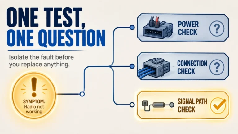
I use one rule throughout this guide: prove each part of the path before replacing anything. That means confirming what enters the radio, what leaves it, what reaches the antenna, and what changes when the station transmits. The broader ham radio setup process begins with the operating goal, but this page starts where a battery-powered handheld stops being the whole system.
Field Note: A station with no documented baseline creates several believable explanations for every symptom. A station with known supply voltage, current capacity, feedline condition, SWR behavior, and noise level usually narrows the same problem to one or two checks.
Station-type priority: A fixed base station usually puts feedline loss, bonding and lightning planning, and documented RF exposure near the front because the installation stays in place. A mobile station moves power routing, fuse placement, coax routing, antenna bonding, and vehicle safety higher on the list. A portable station often starts with battery limits, connector strain, temporary feedline routing, antenna verification, and an RF exposure assessment for the actual field layout. The same station paths apply to all three; the order of attention changes with the installation.
This guide does not choose a radio or antenna for you, and it does not replace the exact equipment manuals, local electrical requirements, or qualified professional work. Antenna selection and physical mounting belong in the antenna setup planning guide. Here, the goal is to make the supporting station paths compatible, safe, and diagnosable. These ham shack basics are less visible than the radio display, but they determine whether the station remains dependable under real load.

BTECH RPS-50PRO supplies regulated DC for radio-station equipment with a fixed 13.8V option and adjustable 9–15V output. Its front panel includes Anderson Powerpole, USB-C, and cigarette-plug connections, while the LCD reports voltage and current in real time. The unit is rated for 50A continuous output and includes a noise-offset control, making it useful when building and documenting a station power baseline.
Check On AmazonIf you click this link and buy, we earn a commission at no additional cost to you.
Start With the Power Path, Not the Power Switch
A radio turning on proves only that some voltage reached it with little load. Transmitting is the more demanding test because current demand rises, wiring losses matter more, and a marginal connection may heat up or drop enough voltage to make the radio reset, reduce output, distort audio, or shut down. The supply, battery, vehicle circuit, fuse, cable size, connector, and return path must be treated as one circuit.
Begin with the voltage range and current requirements in the exact radio manual. Distinguish normal receive demand from maximum transmit demand, then confirm that the source can supply the required current continuously for the intended operating pattern, not just produce a larger number on its label for a moment. A regulated source must also remain within the radio’s allowed voltage range under load and should not add switching noise that raises the receiver noise floor.
| Power check | What it prevents | What changes the answer |
|---|---|---|
| Manual voltage range | Undervoltage resets and overvoltage damage | Radio model and operating mode |
| Continuous current capacity | Supply shutdown, voltage sag, and overheating | Transmit power and duty cycle |
| Fuse location and rating | Unprotected wiring during a short circuit | Wire run, source, and manufacturer instructions |
| Wire size and connector condition | Excess voltage drop and hot connections | Current, run length, routing, and environment |
| Noise check | A power source masking weak received signals | Band, load, grounding, and nearby electronics |
The table is a decision sequence, not a universal wiring specification. Vehicle systems add battery state, alternator behavior, existing circuit limits, airbag paths, and safe cable routing. Battery stations add chemistry-specific charging, low-voltage limits, ventilation, and short-circuit protection. The detailed radio power supply setup should be used before choosing wire, fuses, connectors, or a vehicle power route.

BTECH RPS-30M converts 110V AC to regulated 13.8V DC for radio and other 13.8V station equipment. It is rated for 25A continuous output with 30A peak capacity and provides a cigarette-lighter port plus post screw terminals. The published specifications list less than 2 percent output-voltage regulation and less than 100 mVp-p ripple and noise, making it a practical source for checking station behavior under transmit load.
Check On AmazonIf you click this link and buy, we earn a commission at no additional cost to you.
Treat Coax and Connectors as Active Parts of the RF Path
Feedline does not merely connect the radio to the antenna. It carries transmitted power in one direction and weak received signals in the other, while adding loss to both. That loss depends on the cable type, frequency, length, condition, and mismatch, which is why a short run that is acceptable at HF may be a poor choice for a long VHF or UHF installation.
Impedance must match the system the equipment expects, but the number printed on the cable jacket is not the whole decision. Published attenuation should be checked at the highest frequency and actual length you plan to use. Outdoor exposure, crushed sections, tight bends, damaged shielding, water entry, and poorly installed connectors can make an installed run perform worse than its new-cable specification.
Adapters deserve the same scrutiny. One compatible adapter used for a clear purpose is different from a chain of adapters supporting cable weight behind the radio or exposed to weather. Each added junction creates another possible loose contact, impedance discontinuity, moisture path, and mechanical failure point, so the correct target is not zero adapters at any cost but the fewest reliable transitions the installation genuinely needs.
Research-based: Verify connector families, cable loss, minimum bend radius, outdoor rating, and weather-sealing requirements from the cable and connector documentation. Do not use a generic bend rule or assume two connectors are compatible because they appear to fit.
Plan the complete run before cutting or routing anything. The coax and connector selection guide explains how frequency, distance, connector type, adapters, water protection, and mechanical routing change the right choice. This prevents a common station mistake: buying the feedline by diameter or reputation, then discovering that its loss, stiffness, or connector plan does not fit the site.

STEREN model 205-750 is a 50-foot RG8X coaxial cable fitted with PL-259 UHF male connectors at both ends. The selected cable is specified for 50-ohm systems and arrives as a completed male-to-male coax assembly. Its fixed 50-foot length gives a concrete feedline option for installations where RG8X loss, routing, connector type, and environmental requirements have already been verified.
Check On AmazonIf you click this link and buy, we earn a commission at no additional cost to you.
Use SWR as a Diagnostic Clue, Not a Station Score
SWR describes the relationship between forward and reflected waves on a transmission line. It helps reveal an impedance mismatch, but it does not directly prove that an antenna radiates efficiently, that the feedline has low loss, or that the pattern reaches the station you want. A low reading can exist with a lossy system, while a usable antenna system may show different readings across its intended frequency range.
Measurement location changes what the instrument sees. A meter at the radio end includes the behavior of the feedline between the meter and antenna, and feedline loss can make a severe mismatch at the antenna appear less dramatic in the shack. An analyzer connected at a different reference point is answering a different question, which is why instrument placement should be written down with the result.
Calibration, frequency, test power, and instrument limits also matter. Use the procedure for the exact analyzer or meter, keep transmitted test power within its rating, and avoid making adjustments while someone could contact the antenna or while the antenna system is unsafe to access. A change in SWR after rain, movement, or cable handling is often more informative than one isolated number because it points toward moisture, a loose connection, mechanical stress, or an intermittent conductor.
The next step is not to turn every matching control until the radio stops complaining. Use the detailed SWR measurement and diagnosis process to place the instrument correctly, establish a safe test level, and separate antenna, feedline, and connector problems. The result should tell you what to inspect next, not merely produce a number to record.

Mcbazel Surecom SW-102 is a digital antenna power and SWR meter specified for 125–525 MHz VHF and UHF operation. It displays SWR together with forward and reflected power, allowing readings to be tied to a defined test frequency and meter location. The meter uses a direct digital readout without a manual calibration step, giving a repeatable instrument for comparison tests within its rated frequency range.
Check On AmazonIf you click this link and buy, we earn a commission at no additional cost to you.
Separate Electrical Safety, Bonding, RF Current, and Lightning Protection
The word ground is often used as though it describes one wire that solves every station problem. It does not. AC electrical safety, equipment bonding, unwanted RF-current management, and lightning protection serve different purposes, and a conductor or layout that helps one purpose may be ineffective or unsafe for another.
AC safety grounding belongs to the building’s electrical system and protects against shock when a fault energizes exposed equipment. Bonding limits voltage differences between connected conductive parts. RF-current control addresses unwanted current on feedlines, equipment cases, control cables, or other conductors. Lightning protection manages a high-energy transient through a coordinated entrance, bonding, and grounding system that must match the site and applicable code.
A separate rod added casually outside the station can create a dangerous voltage difference if it is not bonded as required to the building grounding electrode system. Likewise, a wire called an RF ground is not a substitute for electrical safety grounding or a designed lightning path. This is one reason internet diagrams cannot be copied safely without knowing the building service, electrode system, cable entrances, soil, structure, and local requirements.
Warning: Do not design or modify mains wiring, grounding electrodes, bonding conductors, surge protection, or lightning systems from a general article. Use the station grounding and lightning guide to identify the required decisions, then involve a qualified professional and local code authority when the work affects the building electrical or lightning-protection system.
No grounding arrangement makes it safe to work on an antenna during a storm or near overhead power lines. Plan shutdown and disconnection methods before severe weather arrives, and keep outdoor access off the list once thunder is present. Safety is the gate that stops the project, not another variable to test after the station is on the air.

Grounding and Bonding for the Radio Amateur, Second Edition, by Ward Silver brings station grounding and bonding material together for amateur-radio installations. It covers AC electrical safety, lightning protection, and management of RF currents and voltages rather than treating ground as one universal connection. The material is aimed at new station builders and operators upgrading an existing station, closely matching the need to separate these safety and RF functions.
Check On AmazonIf you click this link and buy, we earn a commission at no additional cost to you.
Complete the RF Exposure Check for the Actual Configuration
RF exposure compliance belongs in the station plan before routine transmitting, not after the antenna location is fixed. The operator must assess the station configuration under current FCC requirements. The first question is whether the configuration meets an applicable exemption from further evaluation; if it does not, the station needs a routine evaluation using an accepted calculation or measurement method.
The assessment depends on more than transmitter output. Frequency, power delivered to the antenna, antenna gain and pattern, operating mode, transmit duty cycle, distance to people, and whether exposure is controlled or uncontrolled can all affect the result. A safe conclusion for one band or mode should not be copied automatically to another.
Keep a record of the inputs, method, result, assumptions, and date. The record does not need to become a complicated engineering report to be useful, but it should be clear enough to show why the station was considered compliant. Reassess when a change could increase exposure, such as higher power, more antenna gain, a different antenna location, a higher-duty-cycle mode, reduced separation, or a new area accessible to other people.
Key point: A low SWR result is not an RF exposure evaluation. SWR addresses mismatch in the RF path, while exposure analysis addresses the field people may encounter around the transmitting antenna.
The RF exposure safety evaluation guide walks through the exemption decision, routine evaluation inputs, documentation, and reassessment triggers. When the antenna is close to occupied areas, uses an unusual pattern, or falls outside the limits of a simple calculator, stop and obtain qualified RF-safety assistance rather than forcing the configuration into a simplified model.
Troubleshoot the Station as a Chain
Amateur radio station troubleshooting becomes much faster when the symptom is assigned to a path before parts are swapped. No power points first toward the source, fuse, wiring, connector, and radio protection. No receive may involve squelch or settings, but it may also be feedline loss, an antenna fault, local noise, or a disconnected accessory. A repeater access failure is different from reaching the repeater but receiving no reply.
Change one variable at a time and record the result. If the supply, coax, antenna, location, settings, and test frequency all change together, a successful result does not reveal which change fixed the fault. A known-good substitute can be useful, but only when it is electrically compatible, safe for the test, and introduced at a clearly defined point in the path.
| Symptom | First path to verify | Do not assume |
|---|---|---|
| No power | Source, fuse, polarity, wiring, and connector | The radio failed internally |
| No receive | Settings, noise level, feedline, and antenna connection | The frequency is inactive |
| Repeater does not open | Verified access settings, path, and transmitted signal | No reply means no access |
| No one replies | Monitor activity, signal report, timing, and operating context | The station cannot transmit |
| High or changing SWR | Connectors, moisture, cable movement, and antenna condition | The radio caused the mismatch |
| RF feedback or device upset | Common-mode paths, bonding, cable routing, and power leads | A different microphone will solve the system |
| Intermittent fault | Mechanical stress, heat, loose contacts, and supply sag | An intermittent result cannot be reproduced |
A useful baseline includes receive noise with the antenna connected and disconnected, supply behavior during receive and transmit, SWR at selected frequencies, and a description of the station configuration. It gives later changes something concrete to compare against. Follow the station troubleshooting decision path when a symptom appears, especially before buying replacement equipment.

Klein Tools MM325 is a manual-ranging digital multimeter that measures AC/DC voltage up to 600V, DC current up to 10A, and resistance up to 2 MΩ. It also provides continuity, diode, and battery tests with a backlit display and Lead Alert indicators for test-lead placement. The meter includes test leads, batteries, and a user manual, giving a compact instrument for controlled station power and continuity checks.
Check On AmazonIf you click this link and buy, we earn a commission at no additional cost to you.
A Complete Ham Radio Station Setup Checklist
A first ham radio station is ready for regular use when the supporting paths have documented answers, not when every accessory space on the desk is filled. The checklist below is intentionally system-based. It prevents the common situation in which each component looks reasonable by itself but two adjacent parts are electrically, mechanically, or operationally incompatible.
Research-based station audit: Complete each item from the exact manuals, cable documentation, site conditions, current rules, and applicable codes. This is a verification checklist, not a substitute for model-specific instructions or professional design.
- Exact radio manual: Keep the correct revision and confirm voltage range, maximum current, fuse requirements, connector assignments, grounding instructions, and operating limits.
- Supply capacity: Verify regulation and continuous current under the intended transmit load, with enough margin for safe operation without relying on a momentary peak claim.
- Fused wiring: Confirm polarity, conductor size, route, strain relief, source protection, and fuse placement using the equipment instructions and site requirements.
- Compatible connectors: Check electrical type, gender, mechanical support, installation quality, and the minimum number of necessary adapters.
- Feedline loss: Calculate or verify loss for the actual cable type, frequency, and length, then inspect routing, bend radius, weather exposure, and water protection.
- Antenna verification: Confirm that the antenna system is intended for the band and installation, then record SWR or analyzer results at defined frequencies and measurement points.
- Grounding and lightning plan: Separate AC safety, bonding, RF-current control, and lightning protection, with professional and code review where required.
- RF exposure basis: Record whether the configuration meets an exemption or requires a routine evaluation, along with inputs, result, and reassessment triggers.
- Documented baseline: Save the station diagram, cable routes, fuse values, normal supply behavior, noise observations, SWR readings, and known-good test conditions.
The baseline is what turns the checklist into a diagnostic tool. When a fault appears later, compare the current station with the recorded configuration instead of rebuilding the theory from memory. A change that seemed minor, such as moving a cable, adding an adapter, changing modes, or relocating the antenna, may be the exact detail that separates the previous working state from the new symptom.

Brother P-touch PT-D210 is a portable monochrome label maker with one-touch keys, multiple font styles, and 27 built-in label templates. The package includes a 12 mm black-on-white laminated TZe starter tape and setup guide. It provides a straightforward way to label station cables, connectors, fuse information, and equipment records so a documented baseline is easier to match to the physical installation.
Check On AmazonIf you click this link and buy, we earn a commission at no additional cost to you.
The Safety Gate: Work That Should Stop the Project
Some station tasks are reasonable owner checks, while others cross into electrical, structural, vehicle-safety, fall, lightning, or RF-engineering work. Stop when the task involves mains wiring, service panels, grounding electrodes, structural changes, roof or mast access, uncertain load support, hidden vehicle systems, or drilling where wiring, fuel, airbags, water barriers, or structural members may be present. Local codes and site conditions determine the correct professional handoff.
Never plan an antenna, mast, feedline, or work route that could contact an overhead power line if it falls, swings, or is carried horizontally. Do not climb, disconnect outdoor cables, or work on grounding and lightning hardware during a storm. If the safe clearance, structural capacity, buried services, or vehicle interior path cannot be confirmed, the correct next step is inspection by a qualified person, not a cautious guess.
Stop transmitting during diagnosis when a connector is hot, insulation smells abnormal, a fuse repeatedly opens, voltage or polarity is uncertain, arcing is visible, the radio resets under load, the feedline is damaged, SWR changes sharply without explanation, or people can enter an unevaluated RF exposure area. These signs are not invitations to increase power or bypass protection. They are evidence that the station should remain off until the affected path is understood.
Safety gate: A working contact does not prove that wiring, RF exposure, grounding, structure, or lightning protection is safe. Successful operation and safe installation are separate tests, and both must pass.
Once a task reaches this gate, document the uncertainty and hand it to the person qualified to resolve it. Resume the station build only after the unsafe condition, code question, clearance problem, or structural concern has a verified answer.
Final Thoughts: Build a Station You Can Explain
The strongest version of a station is not the one with the most parts. It is the one whose operator can explain where power comes from, how the circuit is protected, what the feedline loses, where SWR was measured, how safety and bonding are handled, why RF exposure complies, and what the normal baseline looks like.
Complete those answers before adding complexity. When the station changes, update the records and reassess the paths affected by that change. That discipline makes future upgrades safer and turns troubleshooting from random replacement into a controlled comparison.
Explore More Station Infrastructure Guides
Explore more in this section when one part of the station needs a deeper decision process. Each guide below owns a specific path, so you can solve the actual weak point without turning a general checklist into a universal installation recipe.
| Guide | What it helps with |
|---|---|
| Radio Power Supply Setup | Matches voltage, current, regulation, fusing, wiring, noise, and source limits to the radio and installation. |
| Coax Cable and Connectors | Chooses a feedline path by impedance, frequency, length, loss, connector compatibility, and environment. |
| How to Check SWR | Explains instrument placement, calibration, safe test power, interpretation, and fault isolation. |
| Grounding and Lightning Protection | Separates electrical safety, bonding, RF-current control, and site-specific lightning planning. |
| RF Exposure Safety Evaluation | Determines the compliance path, required inputs, documentation, and reasons to reassess a station. |
| Ham Radio Troubleshooting Guide | Diagnoses common power, receive, access, SWR, feedback, noise, and intermittent faults systematically. |
Use the guide that matches the failed path, then return to the complete-station checklist and update the baseline. That keeps each correction connected to the whole station instead of creating a new hidden incompatibility.

The ARRL Antenna Book for Radio Communications, 25th Edition, is a comprehensive reference on antennas, transmission lines, and radio-wave propagation. The softcover edition runs 1,120 pages and carries ISBN-10 1625951760, matching the selected Amazon listing. Its technical scope provides a deeper reference for the feedline, antenna, and propagation subjects connected to the station-infrastructure guides.
Check On AmazonIf you click this link and buy, we earn a commission at no additional cost to you.
FAQs
🔌 How large should my ham radio power supply be?
Use the voltage range and maximum current requirement in the exact radio manual, then choose a regulated source that can supply the intended load continuously with reasonable margin. Do not size it from RF output power or a momentary peak label alone.
📡 Does low SWR mean my antenna system works well?
Not by itself. Low SWR shows a favorable impedance relationship at the measurement point, but it does not prove low feedline loss, good radiation efficiency, a useful antenna pattern, or RF exposure compliance.
🧵 Does coax loss matter on receive as well as transmit?
Yes. Feedline loss reduces power reaching the antenna during transmit and weakens signals traveling from the antenna to the receiver. Frequency, cable type, length, condition, and mismatch affect how much is lost.
⚡ Is one ground wire enough for a ham shack?
There is no universal one-wire answer. Electrical safety grounding, bonding, RF-current management, and lightning protection have different functions, and any connection to a building grounding system must follow applicable code and site requirements.
🛡️ Do all amateur stations need an RF exposure evaluation?
Every station configuration needs a compliance assessment under current FCC requirements. Some configurations may meet an applicable exemption from further evaluation; others need a routine calculation or measurement, and the basis should be documented and reassessed after relevant changes.
🧰 What should I check first when my station stops working?
Classify the symptom, choose the most relevant path, and compare it with the documented working baseline. Verify one variable at a time instead of changing power, cables, settings, and antennas together.
🏠 Can I install the whole station myself?
Owner checks and equipment connections may be reasonable when the manuals and site conditions are clear. Mains wiring, roof or mast work, grounding electrodes, lightning systems, structural changes, uncertain vehicle penetration, and installations near power lines require a qualified professional and local code review.