A safe station power system is not defined by the wattage printed on a supply. The source must stay inside the radio’s specified voltage range while delivering the required current through correctly rated wiring, connectors, and protection. This guide shows how to size and verify that complete DC path for a home station, portable battery, or vehicle installation without treating one setup as universal. You will finish with a repeatable check for voltage drop, heat, noise, fuse protection, and transmit stability.

A Power Supply Is Only One Part of the DC Path
A reliable ham radio power supply setup starts with the radio manual, not the wattage printed on the front of the source. A supply can appear powerful enough and still cause resets, distorted transmit audio, intermittent operation, or excessive connector heat if the voltage, current rating, wiring, or fuse arrangement does not match the radio. The useful question is not merely whether the source turns the radio on. It is whether the entire path remains stable at the radio when transmit current rises.
I use one rule for this part of a station: verify the path in order, from source to protection to cable to connector to radio. That approach keeps a weak crimp, undersized cable, tired battery, or noisy charger from being mistaken for a failed transceiver. It also connects this task to the broader complete ham radio station basics, where power, feedline, antenna match, grounding, RF exposure, and troubleshooting have to work as one system.
Safety limit: This article covers low-voltage DC station power only. Do not open or repair an AC power supply, modify household mains wiring, alter a vehicle charging system, or work around exposed energized conductors unless you are qualified and the work complies with the manufacturer instructions and applicable local code.
That boundary matters because a neat-looking DC installation can still be unsafe if its AC input, vehicle routing, battery protection, or enclosure has been modified without the right knowledge. Keep the work on the user-serviceable side of the equipment, and stop when the manual or local conditions call for a licensed professional.

The TRIcrimp is made for Anderson Powerpole 15, 30, and 45 amp contacts. It is designed to make a positive crimp on those contact sizes. That makes it directly relevant when building or repairing the connector portion of a ham radio DC path.
Check On AmazonIf you click this link and buy, we earn a commission at no additional cost to you.
Read the Exact Radio Manual Before Choosing the Source
The radio manual defines the electrical target. Record the permitted operating-voltage range, the maximum current during transmit, the recommended fuse arrangement, polarity, connector type, grounding guidance, ventilation requirements, and any duty-cycle limits. Do not substitute a value from a similar-looking radio, a forum comment, or a cable label. Two radios with similar output power can place different demands on the source and wiring.
The maximum transmit-current figure is the starting point for sizing, but it is not the only load. Add any equipment that will share the same DC distribution path, such as a control head, interface, tuner, amplifier control circuit, or accessory panel. Keep those loads separate on paper even when they share a source, because the total current and the rating of each branch still have to be known.
| Manual item | What it controls | Why it matters |
|---|---|---|
| Operating-voltage range | Acceptable voltage at the radio | A nominal source voltage is not enough if cable drop pushes the radio below its limit during transmit. |
| Maximum transmit current | Minimum source and path capacity | The source, cable, connector, and distribution hardware must carry the actual load. |
| Fuse instructions | Protection type, value, and placement | Changing the arrangement can leave part of the cable unprotected or defeat intended protection. |
| Polarity and connector | Correct electrical connection | A physically fitting connector is not proof of correct polarity or current rating. |
| Ventilation and duty cycle | Heat management | A source and radio that work briefly may overheat during sustained transmitting. |
Once these values are written down, product labels become easier to interpret. You are comparing a documented station requirement against a source and cable system, not shopping by a single large number.
How Many Amps Does a Ham Radio Power Supply Need?
Start with the radio’s documented maximum transmit current, then add any loads sharing the source. Compare that total demand with the source’s continuous output rating, not only an intermittent, surge, or peak figure. A peak rating may describe what the unit can provide briefly, while a high-duty-cycle operating mode can keep the load elevated long enough for heat and regulation to matter.
Reasonable capacity margin is useful, but there is no universal percentage that fits every supply, enclosure, ambient temperature, or operating pattern. Check whether the rating changes with temperature, whether cooling depends on a fan, and whether the manufacturer specifies a reduced output under certain conditions. A larger number is not automatically safer if the supply has poor regulation, inadequate ventilation, or no credible noise information.
- Use the radio’s maximum documented transmit current as the primary load.
- Add every accessory that shares the same source or distribution branch.
- Confirm that the relevant figure is a continuous rating at the intended voltage.
- Check derating, cooling, ambient-temperature, and duty-cycle conditions.
- Verify that connectors, fuses, and cable are rated for the same current path.
This method prevents two common mistakes: sizing from receive current and sizing from RF output power alone. Neither tells you what the DC path must deliver when the transmitter is working at its highest intended load.

The TP30SWI is a 13.8-volt switching DC power supply with a 30-amp rating. Its analog display gives the operator a quick station-side view of supply output. A noise-offset control is included for shifting switching-related interference when it falls on a receive frequency.
Check On AmazonIf you click this link and buy, we earn a commission at no additional cost to you.
Linear and Switching Supplies Have Different Trade-Offs
A linear supply is usually larger and heavier because of its transformer and heat-dissipation requirements. A switching supply is usually smaller and more efficient, which can make it easier to place and transport. Those differences are real, but they do not justify the shortcut that every switching supply is noisy or every linear supply is clean. Design quality, filtering, load behavior, age, grounding, and nearby equipment can change the result.
For radio use, noise performance has to be measured or documented across the bands you intend to use. A supply can be quiet on one frequency and create birdies, hash, or a raised noise floor elsewhere. Adjustable noise-offset controls can move an interfering signal, but moving it is not the same as eliminating it, and an adjustment should never push the radio outside its permitted voltage range.
| Decision factor | Linear supply | Switching supply |
|---|---|---|
| Size and weight | Usually larger and heavier | Usually smaller and lighter |
| Efficiency and heat | Often lower efficiency with more heat | Often higher efficiency with less heat for the same load |
| RF-noise risk | Not automatically noise-free | Requires credible noise evidence or testing |
| Placement | Needs support and ventilation | Needs ventilation and separation from sensitive cabling |
| Best evidence | Regulation, thermal, and noise performance under load | Regulation, thermal, and noise performance under load |
The practical choice is the supply that meets the voltage and continuous-current requirement, stays cool enough in its installed location, and does not create unacceptable RF noise. The supply type is a clue, not a verdict.

This Astron unit is a linear DC power supply with built-in meters and a 35-amp rating. The meter-equipped design gives the operator direct visibility into supply behavior at the station. It is a useful counterpart to switching models when comparing size, heat, regulation, and RF-noise trade-offs.
Check On AmazonIf you click this link and buy, we earn a commission at no additional cost to you.
Ham Radio DC Wiring Must Control Voltage Drop and Heat
Wire size cannot be selected from current alone. The complete decision includes round-trip run length, conductor material, ambient temperature, bundling, enclosure, connector resistance, and the voltage-drop target permitted by the radio. A cable that is acceptable for a short open run may not be acceptable when it is longer, tightly bundled, routed through a hot vehicle area, or terminated through several adapters.
Check the loaded voltage at the radio end of the cable, not just at the supply terminals. The source may remain steady while a long cable, loose terminal, damaged fuse holder, or underrated connector loses enough voltage to reset the radio during transmit. Secure terminations, strain relief, polarity marking, protected routing, and connector current ratings are therefore part of the electrical design rather than finishing details.
Research-based check: Treat every adapter and detachable connection as another possible resistance point. Use only the number of connections the station actually needs, and inspect each one for secure engagement, discoloration, deformation, looseness, or heat after a defined transmit test.
Do not copy a wire gauge from another station without matching its current, length, installation temperature, and acceptable drop. The right answer is a documented conductor choice for your path, followed by a voltage measurement at the load.
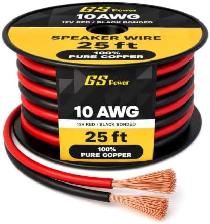
This bonded cable uses 10 AWG stranded oxygen-free copper conductors for low-voltage DC wiring. The red and black pair provides 25 feet of each conductor, for 50 feet total. Its paired polarity colors suit custom station leads where wire gauge, run length, termination quality, and voltage drop still need to be verified for the actual load.
Check On AmazonIf you click this link and buy, we earn a commission at no additional cost to you.
Fuses Protect Wiring, but the Arrangement Is Model-Specific
A fuse does not make an undersized cable safe, and a fuse placed far from a battery can leave the upstream section unprotected. Follow the radio, power-source, battery, and vehicle instructions for fuse value, type, placement, and whether both conductors require protection. Do not remove an original inline fuse because another fuse exists at the supply or distribution block unless the manufacturer explicitly approves that arrangement.
Battery-fed circuits deserve special care because a battery can deliver very high fault current into a short circuit. Protect exposed terminals, prevent tools or loose metal from bridging them, secure the battery against movement, and use connectors that cannot be reversed accidentally. Reverse-polarity protection inside a radio is not permission to ignore polarity marking or connector keying.
Choose a larger fuse when the original fuse opens, then continue transmitting without finding the cause.
Stop, de-energize the circuit, inspect the cable and load, and replace the fuse only with the specified type and rating after the fault is understood.
If a fuse opens repeatedly, the installation has a fault or a mismatch that must be diagnosed. Escalating the fuse value can turn a manageable failure into damaged wiring, a melted connector, or a battery fire.

The Blue Sea Systems 5026 provides 12 ATO or ATC fused branch circuits with a negative bus and clear cover. Its block rating is 100 amps, with up to 30 amps per fused branch. It provides organized DC distribution while leaving the actual fuse size and placement to the radio, source, battery, and vehicle instructions.
Check On AmazonIf you click this link and buy, we earn a commission at no additional cost to you.
How to Power a Mobile Radio at Home
To power a mobile radio at home, use a regulated DC source that matches the radio’s specified voltage range and maximum transmit current. A 13.8-volt ham radio power supply is common for equipment designed around a nominal vehicle electrical system, but the exact permitted range still comes from the manual. Check the supply’s continuous rating, connector compatibility, ventilation, and RF-noise performance before treating it as suitable.
An accessory socket or small plug-in adapter should not be the default merely because the connector is convenient. Its current rating, internal wiring, fuse, contact area, and duty-cycle capability may be below what the radio demands during transmit. The radio may receive normally and even transmit at low power while still failing at a higher load.
Field Note: A radio that receives normally but reboots, dims, or loses audio on transmit is not proof that the transceiver has failed. Capture the radio’s input voltage during the failure before replacing equipment.
Before selecting the source, confirm the current demand of the radio you intend to use. The same check applies whether you are choosing a mobile radio by use case or choosing an HF radio by use case, because the power path should be sized for the actual radio rather than an assumed category average.
Battery and Portable Sources Need More Than an Amp-Hour Label
A battery has to match the radio’s voltage range throughout its usable state of charge, not only when fully charged. Check the chemistry, discharge curve, continuous discharge rating, battery-management system limits, approved charge method, connector rating, and low-voltage behavior. An amp-hour label alone does not reveal whether the battery can support the radio’s peak current or how long it will remain above the radio’s minimum voltage.
Runtime estimates should use the station’s actual operating pattern. Receive current, transmit current, transmit power, mode, accessory loads, temperature, and battery age all affect the result. Use watt-hours or a documented capacity curve when available, then verify the estimate with a controlled field test instead of treating it as a guarantee.
- Use a charger approved for the battery chemistry and configuration.
- Confirm the battery-management system can support the intended continuous and peak load.
- Protect the positive terminal and any exposed distribution points from short circuits.
- Secure the battery and cables against movement, abrasion, and connector strain.
- Follow current storage and transport rules for the battery type and destination.
Backup and field power: Treat a portable solar charger or generator-fed supply as another part of the source path, not as guaranteed clean power. Test the station first on the battery alone, then reconnect the controller, charger, inverter, or regulated supply one component at a time and compare voltage stability, heat, shutdown behavior, and receive noise. Use each device only as documented. This guide does not cover generator repair, fuel storage, household transfer equipment, mains backfeeding, or homemade AC wiring; those tasks require the proper equipment and professional handoff.
Stop using a battery that is swollen, leaking, physically damaged, unusually hot, or behaving outside its documented limits. Do not charge it unattended in an unsuitable location, and do not improvise around a battery-management fault. Record the tested backup configuration before depending on it during an outage or field deployment.
The Vehicle Power Path Must Respect the Vehicle
A vehicle installation has to account for battery condition, alternator capacity, start-stop behavior, voltage variation, protected cable routing, ignition control, and the vehicle manufacturer’s two-way-radio guidance. Do not assume that a convenient fuse-panel position, accessory socket, or chassis point can support the radio. Modern vehicles may include battery-current sensors, supplemental-restraint wiring, control modules, and routing restrictions that change the correct connection method.
Follow both the radio manual and the vehicle manufacturer’s instructions. Fuse and protect the conductors as directed, keep wiring away from heat, sharp edges, moving parts, pedals, steering components, and airbag deployment paths, and use an existing approved pass-through where available. Firewall penetration, trim removal near safety systems, battery-sensor connections, or structural changes are professional-installation territory when the correct route is not documented.
Stop condition: Do not drill through a firewall, floor, structural support, roof, or body panel until the hidden structure, wiring, fuel or brake components, corrosion protection, and safety systems have been positively identified. Use a qualified installer when the route or vehicle guidance is unclear.
The power route and antenna route also have to coexist without creating interference or physical hazards. Plan them together with a safe mobile antenna installation, but keep the electrical and RF requirements distinct during diagnosis.
Diagnose Noise and Voltage Sag by Changing One Variable
Power problems do not always look electrical. A noisy supply or charger may raise the receive noise floor, create repeating tones, or place narrow signals across part of a band. A weak DC path may cause transmit resets, display dimming, low output, audio distortion, or intermittent behavior. Hum can come from a power source, an audio connection, shared grounding, or another device connected to the station.
Start with a documented baseline, then change one variable at a time. Note the band, frequency, mode, power level, source, accessory state, and whether the symptom appears on receive, transmit, or both. Disconnect nonessential accessories, turn chargers and nearby switching devices off one at a time, and compare the result with a known clean source that is electrically suitable for the radio.
| Symptom | First measurement | Next isolation step |
|---|---|---|
| Radio resets on transmit | Voltage at the radio during transmit | Inspect cable, fuse holders, connectors, and source regulation under load. |
| Receive noise changes with supply | Noise baseline by band and frequency | Compare with a known clean source and disconnect nearby chargers. |
| Connector becomes warm | Temperature after a defined load | De-energize and inspect rating, contact pressure, crimp, corrosion, and strain. |
| Audio hum appears | Whether hum changes with accessories | Remove one audio or data connection at a time and retest. |
| Intermittent power | Voltage while gently checking the stationary cable path | Inspect for loose contacts, damaged conductors, and unsupported connectors. |
When the symptom does not isolate cleanly, move into systematic ham radio troubleshooting rather than replacing components at random. The goal is to preserve evidence until the failing part of the path is known.
Verify the Power Path Before You Trust It
A station that powers on has passed only the first test. Verification should show that the source stays regulated, the radio input remains within the manual’s range during transmit, and no cable, connector, fuse holder, or distribution point develops abnormal heat. The check also needs a noise baseline so a later interference problem can be compared with a known state.
Perform the test under a defined and lawful load using the radio and antenna system as instructed by their manuals. Keep transmit tests brief enough to respect duty-cycle and thermal limits, and use a suitable load or antenna arrangement for the measurement being made. Do not transmit into an unknown or disconnected RF path simply to load the power supply.
- Confirm source voltage with no load and with the radio receiving.
- Record the radio-end voltage during the intended transmit load.
- Verify current using a properly rated instrument and safe measurement method.
- Inspect fuse values, fuse holders, polarity, connector engagement, and strain relief.
- Check cables and connectors for abnormal heat after the defined test.
- Record the source, cable length, connector path, load, voltage, current, and ambient conditions.
- Record a receive-noise baseline on the bands the station will use.
Research-based baseline: Save the measurements and a simple wiring diagram with the radio manual. When the station changes, repeat the same checks instead of assuming the old result still applies.
This record turns future faults into comparisons. A later reset, new noise signal, warm connector, or lower transmit voltage can be measured against a known working configuration instead of reconstructed from memory.

The AstroAI CM600 measures AC and DC current along with AC and DC voltage. Its 6000-count True RMS design also includes inrush-current measurement, resistance, frequency, capacitance, and continuity functions. Those capabilities fit the article verification step for recording radio-end voltage and checking current with a properly rated instrument.
Check On AmazonIf you click this link and buy, we earn a commission at no additional cost to you.
Know Where the DIY Power Work Must Stop
Low-voltage DC does not mean unlimited fault energy, especially around storage batteries and vehicle electrical systems. Stop when the work requires opening an AC supply, modifying a listed product, changing household wiring, altering an alternator or charging circuit, bypassing a battery-management system, or working around damaged high-current conductors. Those tasks need the correct professional, manufacturer procedure, and local code review.
The same handoff applies when a vehicle route crosses a firewall or safety system, when a battery installation lacks documented ventilation or protection, or when the correct fuse and chassis connection cannot be established from the manuals. A professional installation is not a failure to understand ham radio. It is the correct response when the station work moves beyond user-serviceable DC connections.
Power is only one part of setting up a ham radio. Once the DC path is verified, the antenna system, feedline, grounding or lightning plan, RF exposure evaluation, programming, and operating path still need their own checks.
Final Thoughts: Verify the Entire Path Under Load
The unloaded display on a source proves very little by itself. A useful final check places the intended demand on the station and confirms that the radio input stays within specification while the supply, cable, fuses, connectors, and terminations remain stable and cool.
Start with the exact manual, size from continuous current, protect the wiring as directed, and document the baseline. When a problem appears, change one variable at a time. That process is slower than guessing for a few minutes and much faster than replacing the wrong part.
FAQs
⚡ What voltage should a ham radio power supply provide?
Use the operating-voltage range in the exact radio manual. Many mobile-style radios are designed around a nominal 13.8-volt source, but the acceptable range and required regulation are model-specific.
🔌 How many amps should I allow for my radio?
Start with the radio’s documented maximum transmit current, then add accessories sharing the same source. Compare the total with the supply’s continuous rating under the intended temperature and cooling conditions.
📻 Can I use a mobile radio from a home outlet?
Not directly. Use a regulated AC-to-DC supply that matches the radio’s voltage, continuous-current, connector, fuse, ventilation, and noise requirements.
🔋 Can a battery power a base or mobile transceiver?
Yes, when its voltage range, continuous discharge capability, battery-management limits, connector, fuse protection, and charge method match the radio. Estimate runtime from the real operating pattern and verify it under controlled conditions.
🚗 Should I power a vehicle radio from the accessory socket?
Do not assume the socket can support the load. Follow the radio and vehicle manufacturer instructions, including current limits, fuse placement, routing, battery-sensor guidance, and any requirement for a direct protected connection.
🌡️ Why does a DC connector become warm?
Heat can indicate excessive current, poor contact pressure, corrosion, a weak crimp, an underrated connector, or strain on the connection. De-energize the path and inspect it before continuing to transmit.
🎚️ Why does my radio reset only on transmit?
Watch the radio’s input voltage during transmit. A source that looks normal with no load may sag through an undersized cable, loose connector, weak battery, damaged fuse holder, or inadequate supply.
📶 Can a power supply cause radio interference?
Yes. Supplies, chargers, and nearby switching devices can create broadband noise or narrow signals, but the design type alone does not prove the cause. Compare the station with a known clean source and isolate one device at a time.