Moving from 25W to 50W doubles transmitter power, but it adds only about 3 dB to the outgoing signal, not twice the range. A 65W setting adds about 4.15 dB over 25W and only about 1.14 dB over 50W, so the practical difference depends on the antenna system, terrain, feedline loss, supply voltage, receiver conditions, and duty cycle. Extra power can add useful link margin when a path already works, but it cannot repair a blocked path, damaged coax, poor antenna placement, severe noise, or an unsuitable communication plan. Choose the output level that the complete installation can support reliably instead of treating the largest wattage number as the automatic winner.

Doubling Power Does Not Double Mobile Range
Mobile ham radio power output is easy to compare on a product page because 25W, 50W, and 65W look like clean steps. The mistake is assuming those numbers produce equally large steps in real communication distance. Radio links are governed by decibels, path loss, antenna pattern, terrain, receiver performance, and local noise, so wattage alone cannot provide a dependable mileage figure.
I start with the complete path rather than the number on the front of the radio. If a 25W signal already reaches a local repeater with clean audio, 50W may add no useful operating result. If the signal is close to the receiver’s usable threshold, the extra 3 dB can be enough to improve quieting or readability, but only because the rest of the path was already nearly workable.
Key point: Treat wattage as a diagnostic variable, not the first response to a failed contact. Confirm the frequency, endpoint, antenna system, supply voltage, and terrain before deciding that the transmitter needs more output.
This article is limited to power decisions for beginner-to-intermediate VHF and UHF mobile operation. It does not rank individual radios, promise a fixed range, or replace the detailed selection work in my guide to choosing a mobile ham radio.

The AnyTone AT-778UVII is a dual-band 25W mobile transceiver for 2m and 70cm operation. The listing includes a programming cable and identifies VOX support. It is designed as a mini mobile radio for vehicle use.
Check On AmazonIf you click this link and buy, we earn a commission at no additional cost to you.
Read the Wattage Difference in Decibels
The useful calculation is 10 times the base-10 logarithm of the new power divided by the old power. You do not need to perform that calculation while driving or shopping, but knowing the results prevents the most common misunderstanding: a large percentage increase in watts can become a modest increase in signal level.
| Power change | Wattage increase | Signal-level change | Practical meaning |
|---|---|---|---|
| 25W to 50W | 100 percent | About 3.01 dB | A useful margin near a threshold, not double the range |
| 25W to 65W | 160 percent | About 4.15 dB | More margin than 50W, but still a modest link-budget change |
| 50W to 65W | 30 percent | About 1.14 dB | Usually a small difference unless the path is very close to failure |
| 25W to 100W | 300 percent | About 6.02 dB | Four times the power, not four times the communication distance |
The 50W-to-65W comparison is the one buyers often overestimate. Sixty-five watts sounds substantially larger on a specification sheet, yet the mathematical advantage over 50W is only about 1.14 dB when every other variable remains identical. That difference is measurable, but it may be difficult to notice on a strong FM path that is already fully quieted.
Near the edge of usable FM coverage, a few decibels can matter more because the receiver may be moving between noisy and readable audio. Even there, the result is conditional. The same power change can appear helpful at one location and irrelevant a few yards away if a ridge, building, vehicle body, or multipath reflection changes the signal.
What Additional Transmitter Power Can Improve
Extra output changes the amount of RF arriving at the distant receiver. When the path is already viable, that added signal can increase fade margin, improve FM quieting, and keep speech readable through small variations in vehicle position or foliage. The benefit appears at the receiving end, not as a new capability inside the transmitting radio.
| Receiver condition | What more power may change | What it does not change |
|---|---|---|
| Noisy but repeatable FM audio | May improve quieting and intelligibility when the carrier is close to the usable threshold | Does not remove noise generated at the receiving site |
| Intermittent repeater access with the correct tone or code | May give the receiver more margin to detect the carrier and its correctly transmitted access signal | Does not fix a wrong CTCSS tone, DCS code, offset, or frequency |
| Brief fades along a known route | May keep the signal above threshold through smaller path changes | Does not eliminate a deep terrain shadow or blocked line of sight |
| Already full-quieting audio | May add reserve margin that is not audible during the test | Usually does not make clear FM audio sound noticeably clearer |
The access-tone case deserves care. Higher power raises the whole transmitted signal, including the correctly encoded tone or code, so a marginal receiver may decode it more consistently. It does not alter the tone level relative to the voice, and it cannot rescue incorrect programming. A station that opens the repeater only after switching to high power may still need its frequency, offset, tone, antenna, and supply voltage checked.
The United States amateur rules require using the minimum transmitter power necessary to carry out the desired communication. High power remains available when the path needs it, but the useful operating habit is to establish the contact at the lowest dependable setting and preserve the higher setting as margin for harder conditions.
Research-based field note: When I evaluate a weak mobile path, I separate three questions before blaming wattage: Is RF reaching the intended receiver, does the radio hold proper voltage while transmitting, and is the antenna-feedline system behaving normally? That sequence reveals whether the missing margin is actually a power problem.
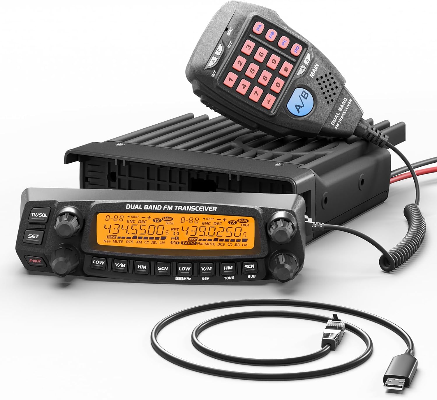
The Radioddity DB50 is a 50W dual-band VHF/UHF mobile transceiver. It has a detachable front panel and supports CHIRP programming with the included programming cable. The listing specifies 758 channels plus CTCSS/DCS and multiband receive coverage.
Check On AmazonIf you click this link and buy, we earn a commission at no additional cost to you.
What More Watts Cannot Repair
A transmitter cannot force a VHF or UHF signal through every obstacle. If a mountain blocks the path, moving from 25W to 65W may add a few decibels to a signal that is still far below the receiver threshold. Changing location, gaining elevation, using a reachable repeater, or choosing another communication path can matter more than the extra RF output.
More power cannot correct any of the following faults:
- A wrong band, frequency, offset, access tone, or operating mode
- No active repeater or no station monitoring the chosen simplex frequency
- Poor antenna placement inside the vehicle or beside obstructing metal
- A loose connector, water-damaged feedline, pinched cable, or excessive SWR
- Severe electrical or RF noise at the receiving end
- Receiver desense or overload caused by another nearby transmitter
- A communication plan that depends on an operator or system that is not available
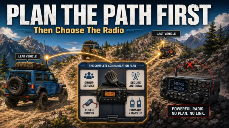
The last point is easy to miss. A powerful radio does not create an endpoint. If the goal is vehicle-to-vehicle coordination, every vehicle needs a compatible plan and an authorized operator. If the goal is repeater access, the repeater has to be active and reachable from the actual route.
A Link-Budget Example Shows Why the Whole System Matters
The following example is deliberately simplified. It compares only the transmitter, feedline, and effective antenna gain toward the intended station. Receiver antenna gain, path loss, terrain, polarization, vehicle body effects, local noise, and receiver sensitivity are held constant so the effect of each change stays visible.
| Example system | Transmitter output | Feedline loss | Effective antenna gain toward target | Relative launch level |
|---|---|---|---|---|
| A: Basic 25W system | 44.0 dBm | 1.5 dB | 2.0 dBi | 44.5 dBm EIRP |
| B: Same system at 50W | 47.0 dBm | 1.5 dB | 2.0 dBi | 47.5 dBm EIRP |
| C: Same system at 65W | 48.1 dBm | 1.5 dB | 2.0 dBi | 48.6 dBm EIRP |
| D: Improved 25W path | 44.0 dBm | 0.5 dB | 5.0 dBi | 48.5 dBm EIRP |
Under those stated assumptions, improving the feedline by 1 dB and adding 3 dB of effective antenna gain in the required direction gives the 25W system about the same transmit-side result as the original 65W system. This is not a promise that one antenna will always beat another radio. Antenna gain comes from reshaping the radiation pattern, and a flatter pattern that helps across level terrain can perform worse when the target is above the vehicle or hidden by steep terrain.
Ground plane, mounting position, vehicle body coupling, cable routing, connector quality, and band all change the result. That is why a useful mobile antenna selection process starts with the vehicle and operating path rather than a gain number by itself.
The installation matters just as much as the antenna label. A technically capable antenna mounted where the vehicle body blocks or distorts it may underperform a more modest design installed correctly. My guide to installing a mobile ham radio antenna covers those placement, grounding, cable-routing, and weatherproofing decisions separately.

The Nagoya UT-72 is a 20-inch magnetic-mount VHF/UHF antenna for 144 and 430 MHz. It uses a PL-259 connector and a heavy-duty magnetic mount. The listing identifies a super loading coil and includes an additional SMA adapter.
Check On AmazonIf you click this link and buy, we earn a commission at no additional cost to you.
The Electrical System Pays for Every Extra Watt
The RF output number is not the radio’s DC input requirement. Dividing 50W by 13.8 volts does not tell you the required fuse or wire size because the power amplifier is not 100 percent efficient and the rest of the radio also consumes power. Use the manufacturer’s maximum transmit-current specification for the exact band and output setting, then design the complete circuit around that figure.
A proper electrical review includes the round-trip conductor length, conductor size, insulation temperature rating, fuse placement, connector rating, vehicle grounding method, alternator capacity, battery condition, and voltage at the radio while transmitting. A long cable run can create enough resistance to lower the voltage at the radio even when the battery appears healthy.
Consider a hypothetical circuit with 0.04 ohm of total resistance and 13 amperes of transmit current. The wiring drops about 0.52 volts and dissipates about 6.8 watts as heat. The exact values in your vehicle will differ, but the example shows why a radio can receive normally and still reduce output, distort, reset, or shut down when high-power transmit current exposes weak wiring.
Cold conditions can expose the same weakness sooner. Battery voltage under load may sag more when the battery is cold, partly discharged, aging, or supporting other vehicle loads, so an installation that holds full output in mild weather may behave differently during winter or engine-off operation. The size of the change depends on battery chemistry, state of charge, temperature, wiring resistance, and the radio’s voltage regulation, so measure at the radio instead of assuming a fixed cold-weather loss.
- Current rating: Use the manual’s maximum transmit draw, not an estimate based only on RF watts.
- Wire length: Count the complete current path, not just the distance from the battery to the radio.
- Fuse location: Protect the conductor close to the power source and follow the supplied harness instructions.
- Connector choice: Use a secure connector rated for the expected current and vehicle environment.
- Voltage test: Measure at the radio during transmission, because an unloaded battery reading can conceal the drop.
- Vehicle guidance: Follow both the radio manual and vehicle service information, especially on vehicles with battery-monitoring or energy-management systems.
A radio advertised at 65W may also provide that output only on one band or only at a stated supply voltage. The UHF rating, lower power steps, and actual output under vehicle voltage may differ. Read the band-specific specification instead of assuming the largest front-page number applies everywhere.
Warning: Do not substitute a vehicle accessory socket for a properly designed power circuit unless the radio manufacturer, socket rating, fuse, connector, and wiring all support the required continuous and peak current. A plug that fits is not proof that the circuit is suitable.
Heat and Duty Cycle Set the Real High-Power Limit
Higher RF output creates more heat in the power amplifier, and long transmissions give the radio less time to cool. A brief voice transmission followed by listening is a different thermal job from repeated data bursts, a long net-control transmission, or a near-continuous carrier. The wattage setting that works for casual FM voice may not be the right setting for a high-duty-cycle application.
Vehicle temperature makes the problem harder. A radio mounted in a closed console, under a seat with blocked airflow, or inside a hot cabin may begin the transmission already near its thermal limit. Fan noise, fan speed, reduced output, thermal protection, or an unexpected shutdown can be symptoms of inadequate cooling rather than a defective RF path.
Use these checks before planning sustained high-power operation:
- Confirm the manufacturer’s operating-temperature and duty-cycle guidance.
- Leave the specified clearance around heat sinks, fan intakes, and exhaust openings.
- Do not let wiring, carpet, equipment bags, or seat material block ventilation.
- Test the intended mode and transmit pattern, not only a short voice call in a cool garage.
- Reduce power when the link remains reliable at a lower setting.
- Stop and diagnose repeated thermal protection instead of defeating it.
The practical trade-off is straightforward: a 65W radio operated at maximum output in a hot, restricted installation may be less dependable than a lower setting the system can sustain. Reliable power is more useful than a peak number that the electrical and cooling system cannot maintain.
Choose the Output Level by Operating Scenario
There is no universal answer to how many watts a mobile ham radio needs. The earlier sections explain what signal margin does; this table turns that information into an operating choice. Select the lowest setting that survives the conditions you actually expect, then verify that the vehicle can supply and cool it.
Research-based recommendation: Start at the lowest setting that provides a repeatable, readable path under the conditions you expect to use. Move higher only after confirming that the antenna, feedline, programming, voltage, and cooling are not the limiting factors.
| Scenario | Reasonable starting approach | Check before increasing power |
|---|---|---|
| Strong local repeater | Use the lowest reliable setting, which may be below 25W | Confirm clean access along the normal route rather than testing only from one high location |
| Marginal rural repeater | Route-test low, medium, and high settings, then keep the lowest one that remains readable through known weak points | Whether the weak points repeat in the same locations and whether voltage remains stable at each setting |
| Simplex convoy | Test the full route at the planned vehicle spacing and reserve higher output for sections where the group actually loses margin | Antenna consistency, route changes, disciplined channel use, and compatible settings in every vehicle |
| Fixed or base use with a mobile radio | Choose power after evaluating antenna height, feedline loss, and the intended station | Power-supply capacity, station grounding, ventilation, and local RF exposure requirements |
| Data or high-duty-cycle use | Use the lowest stable output that supports the path and leaves thermal margin | Mode duty cycle, fan behavior, case temperature, time-out settings, and manufacturer limits |
| Limited vehicle electrical system | Favor 25W or lower until the circuit is verified under load | Transmit current, voltage drop, alternator condition, battery condition, and connector heating |
For a first installation, control layout, mounting, power wiring, receive behavior, and useful low-power steps can matter more than the difference between 50W and 65W. The broader first dual-band mobile radio decision should therefore consider the complete operating role, not just the maximum VHF number.
How to Test 25W, 50W, and 65W Fairly
A casual on-air report can be useful, but it is not enough for a controlled comparison. Moving the vehicle, changing the antenna, testing on different days, or relying on an automatic receiver meter can create a larger variation than the power change you are trying to measure.
Use a repeatable test sequence:
- Fix the path: Keep the transmitting vehicle, receiving station, frequency, mode, antenna, feedline, and surrounding conditions as consistent as practical.
- Verify the transmitter: Use calibrated forward-power and SWR instruments suitable for the band and power level. Record the actual output rather than trusting the menu label alone.
- Check supply voltage: Measure voltage at the radio during each transmission and record the maximum current if suitable equipment and safe access are available.
- Use repeatable receiving evidence: Record receiver audio, quieting, a calibrated field-strength reading, or another method that does not depend solely on one subjective signal report.
- Repeat each setting: Run several short tests at each power level so one fade or burst of interference does not decide the result.
- Document conditions: Note location, band, antenna system, cable, weather, vehicle orientation, battery voltage, and duty cycle.
A repeater signal report can confirm that a setting works, but many repeater systems do not expose a calibrated input measurement to the user. “Full quieting” also leaves little room to hear a 1 dB difference. For a meaningful comparison, test near a stable threshold without creating interference or occupying a shared channel longer than necessary.
The goal is not to prove that high power never helps. It is to identify whether the power increase is the variable producing the improvement. Without that control, a better result may come from vehicle position, antenna pattern, voltage recovery, or a temporary change in the path.

The Surecom SW-102S is a digital VHF/UHF power and SWR meter covering 125 to 525 MHz. This listing uses SO-239 connectors and supports mobile transceivers within its rated frequency and power limits. It provides RF power and SWR measurements for controlled transmitter checks.
Check On AmazonIf you click this link and buy, we earn a commission at no additional cost to you.
Use a Complete-System Decision Before Buying
Maximum wattage belongs near the end of the decision, after the operating path and installation are defined. A 25W radio can be the better fit for a strong local repeater, a compact vehicle, or a limited electrical system. A 50W class radio provides a useful 3 dB step when the path needs more margin. A 65W rating can add another small margin, but the 1.14 dB advantage over 50W should not outweigh poor controls, inadequate cooling, difficult mounting, or an electrical system that cannot support it.
Use this checklist before treating output as the deciding specification:
- Which band and communication path will I actually use?
- Is the target a strong local repeater, a marginal repeater, or simplex?
- What antenna location, ground plane, feedline length, and cable loss will the vehicle allow?
- What is the radio’s maximum transmit current on each relevant band?
- Can the wiring, fuse, connector, battery, and alternator support that load with acceptable voltage drop?
- Will the installation provide enough airflow for the intended duty cycle?
- Does the radio offer useful lower power settings for routine contacts?
- Have I tested the path before paying for power I may not need?
If those answers are not known, return to the complete mobile radio selection framework and define the operating role first. Wattage becomes much easier to judge once the vehicle, antenna system, route, power circuit, and expected contacts are real rather than hypothetical.
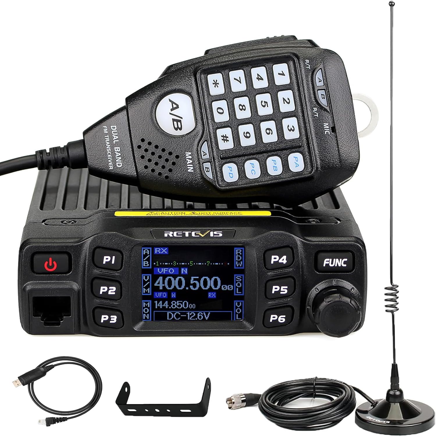
The Retevis RT95 starter kit combines a dual-band 2m and 70cm mobile transceiver with a mobile antenna. The radio has a 180-degree rotatable LCD screen and adjustable microphone gain. The listing also identifies CHIRP programming and DTMF support.
Check On AmazonIf you click this link and buy, we earn a commission at no additional cost to you.
Final Thoughts: Buy Link Margin, Not a Range Promise
I would choose the output level the installation can deliver continuously and the route can prove useful. Improve the largest system weakness first, then pay for additional wattage only when testing shows that a few more decibels solve the remaining problem.
FAQs
📻 Is 50W twice as strong as 25W on ham radio?
It is twice the transmitter power, but the signal-level increase is about 3.01 dB. That can add useful margin near a receiver threshold, but it does not mean twice the range.
⚡ How much stronger is 65W than 50W?
The increase is about 1.14 dB when everything else is identical. It is a modest advantage, so compare band-specific output, current draw, cooling, controls, and installation fit before choosing by that number.
🗻 Will more mobile power get through mountains?
Not reliably. A few extra decibels may help around a marginal obstruction, but a severely blocked VHF or UHF path usually needs a better location, more antenna height, a reachable repeater, or another communication route.
🔌 Why does my radio show less output when the engine is off?
Supply voltage may be lower, and resistance in the wiring, fuse holders, or connectors can create additional drop during transmission. Measure voltage at the radio under load and compare it with the manual’s specified operating range.
🌡️ Can I use maximum power for digital or data modes?
Only when the radio, ventilation, power circuit, and manufacturer limits support the required duty cycle. A lower stable setting often provides better thermal margin for repeated or long transmissions.
📡 Is antenna gain better than adding transmitter power?
Neither is universally better. Antenna gain, pattern, mounting position, ground plane, feedline loss, terrain, and target direction must be evaluated together. A beneficial system change can outperform a small wattage increase, but only under the conditions it was designed for.
🧪 How can I compare two mobile radios fairly?
Use the same antenna system, path, power source, frequency, mode, and test location. Measure actual forward power, SWR, and voltage at the radio, then repeat the receiving test under documented conditions.